Products
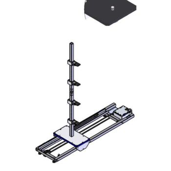
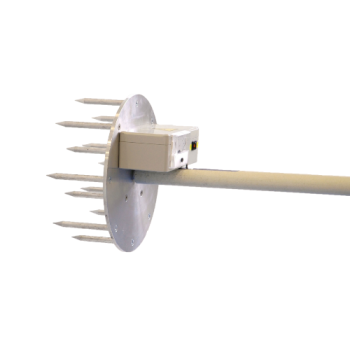
FPP2.3/1.5 M Field Probe Positioner
- Single axial positioner for remote-controlled horizontal movement
- Moves 4 probes 4 times, supper fast 16 piont calibration
- Allows automatic measurements of the field homogeneity according to EN61000-4-3 and IEC61000-4-3.
- Automate uniform field calibration
- Load: 3.0 kg
- Height range 1.0 - 1.5 m
- Manual polarization change 90°
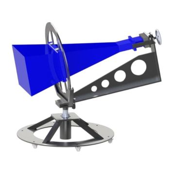
- Antenna Load: 35 kg
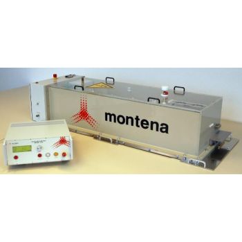
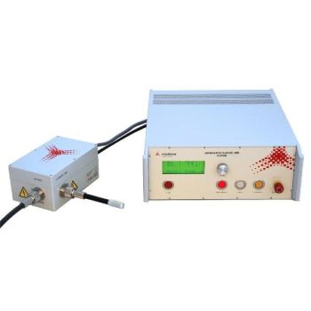
EMP300K-5-500 PCI 5kA Pulse Generator
- MIL-STD-188-125-1/2 Compliant – Ensures precise pulse current injection (PCI) testing for EMP protection validation.
- High-Voltage Performance – Delivers up to 350kV pulses with a peak 5kA short-circuit current.
- Fast & Repeatable Pulses – Ultra-fast and 500-550 ns pulse duration for accurate testing.
- Fully Automated & Computer-Controlled – RS232 & USB interfaces enable seamless remote operation.
- Comprehensive Accessory Support – Compatible with current probes, CDNs, fiber optic links, and automation software for a complete test setup.
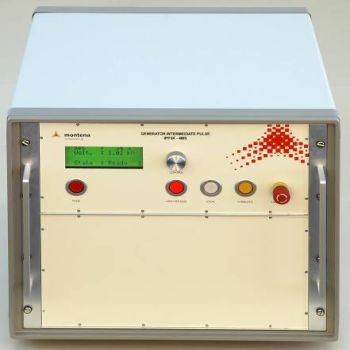
IPP3K-4MS PCI Intermediate Pulse Generator
- MIL-STD-188-125-1/2 Compliant – Designed for precise EMP protection testing.
- High-Voltage Performance – 3.0 kV charging voltage with 260 A peak short-circuit current.
- Fast & Repeatable Pulses – and 3 – 5 ms pulse duration for accurate testing.
- Multi-Line Direct Coupling – 4 independent outputs for testing power, signal, and telecom lines.
- Fully Automated Control – RS232 & USB interfaces for seamless operation & remote testing.
- Complete Testing Solution – Compatible with current probes, CDNs, fiber optic links & optional automation software.
- MIL-STD-188-125-2 Compliant – Designed for pulse current injection (PCI) testing of antenna POE protective devices.
- Adjustable High-Voltage Pulses – 0.2 - 25 kV, 400A (CLP40K) for precise testing.
- Broad Frequency Coverage – Supports testing from 30 MHz up to 477.5 MHz with variable charge line plugs.
- Ultra-Fast Pulse Rise Time – and for high-speed transient testing.
- Direct Coaxial Coupling – No external coupling device required for efficient pulse injection.
- Automated Operation & Remote Control – RS232 & USB interfaces for seamless integration and monitoring.
- Complete Test Solution – Includes charge line plugs, current probes, fiber optic links, and optional Montena PULSELab software.
- MIL-STD-188-125-2 Compliant – Designed for pulse current injection (PCI) testing of antenna POE protective devices.
- Adjustable High-Voltage Pulses – 0.05 - 5 kV, 50Amps (CLP5K) for precise testing.
- Broad Frequency Coverage – Supports testing from 30 MHz up to 477.5 MHz with variable charge line plugs.
- Ultra-Fast Pulse Rise Time – and for high-speed transient testing.
- Direct Coaxial Coupling – No external coupling device required for efficient pulse injection.
- Automated Operation & Remote Control – RS232 & USB interfaces for seamless integration and monitoring.
- Complete Test Solution – Includes charge line plugs, current probes, fiber optic links, and optional Montena PULSELab software.
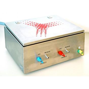
- MIL-STD-461 / RS105 Compliant – Ensures NEMP protection and conducted disturbance testing compliance.
- High Current Capacity – Supports up to 100A continuous operation for demanding test environments.
- Single-Phase & Three-Phase Options – Available in 2-phase (TPD50-100-2) and 4-phase (TPD50-100-4) versions.
- Built-In LISN Channels – Provides accurate measurement of conducted disturbances on connected phases.
- Superior Shielding & Filtering – Feedthrough capacitor filtering minimizes unwanted electromagnetic noise.
- Easy Installation & Mobility – Simple connection setup, compact design, and secure grounding options.
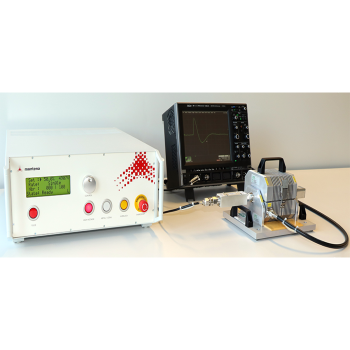
ESD Pulse Generator 10 kV – PESD-ECSS-12K
- High-Voltage Range: 20 V to 10 kV, positive polarity only.
- ECSS Compliant: Meets ECSS-E-ST-20-07C Rev.2 for space-grade ESD tests.
- Damped Oscillatory Waveform: Ensures accurate wire-coupled discharge simulations.
- Remote Control & Monitoring: Offers single shot, repetitive, or remote triggering with RS-232/USB.
- Safety & Reliability: Conforms to EN61010-1 and integrates a 24 Vdc safety loop
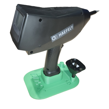
ESD Simulator Stand
- Easily and safely put the ONYX 16 or 30 ESD simulator in an upright position
- 2 holders for Air Discharge & Contact Discharge Tips when not in use
- Firmly holds the base and will not allow the simulator to tip.
- Easy grab-and-go

