
IPG 255, Insulation Tester, 8kV
IPG 506: FRONT-CHOPPED-WAVE GENERATOR
PG 6-364: HV Pulse Generator
IPG 506 SYM: FRONT-CHOPPED-WAVE, 3-Pole DUT

IPG 620/ IPG 1050/ IPG 1272 6kV, 10kV, 12kV
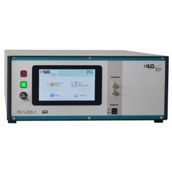
PG 5-200 / PG 10-1000, High Voltage Pulse Generator, 10/700µs, 5/350µs, 1.2/50µs
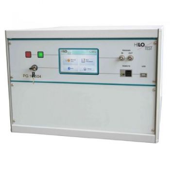
PG 12 - 1440, High Voltage Pulse Generator, 10/700µs, 1.2/50µs, 12kV
PG 14 - 1960, High Voltage Pulse Generator, 10/700µs, 0.5/700µs, 14kV
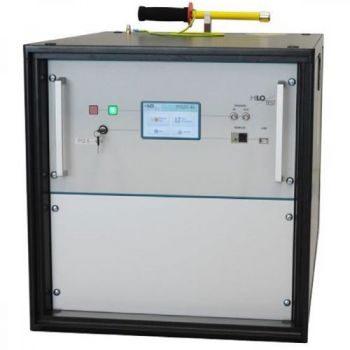
PG 20 - 4000, High Voltage Pulse Generator, 10/700µs, 5/320µs, 20kV
PG 4-641, Impulse voltage, 3600 V
Products
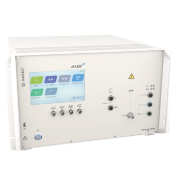
Axos 8 - Compact 7kV Surge, Telecom, Ring Wave, 5kV EFT, Dips/Drops
Axos 8 - Compact
- Multi Tester with 16AMP CDN
- EFT/Burst 5kV IEC 61000-4-4
- Surge, Combination Wave 7kV IEC 61000-4-5
- Surge Magnetic field IEC 61000-4-9 (MSURGE-A loop antenna required)
- Ring Wave, 7kV IEC 61000-4-12 & ANSI
- Telicomm Wave, 7kV IEC 61000-4-5 & ITU
- AC Dips/Drops IEC 61000-4-11 (DIP 116 dips transformer required)
- DC Dips/Drops IEC 61000-4-29 (2x DC supplies required)
IPG 255, Insulation Tester, 8kV
The High-Voltage Pulse Generator IPG 255 is designed for testing of impulse dielectric strength of components, insulation, air-and surface flash-over gaps of watt-hour meters, static relays etc. according to IEC 60255, EN 61036, VDE 0435 part 303. Picture: incl. Option PA 503
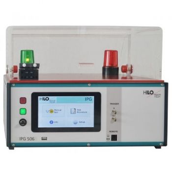
IPG 506: FRONT-CHOPPED-WAVE GENERATOR
The front-chopped-wave generator IPG 506 is used for measuring dc spark-over voltage and impulse spark-over voltage of over-voltage protectors according to CCITT / ITU-T, K12. Dc spark-over voltage: A linearly rising voltage, rate of rise 100 V/s up to 640 V, is connected to the device under test. The spark-over voltage measured is shown in the display. Impulse spark-over voltage: A linearly rising impulse voltage, rate of rise 100 V/µs up to 5000 V/µs, open loop amplitude 5000 V, is connected to the device under test. The spark-over voltage is measured by use of a peak detector. The result is shown in the display. A built-in impulse voltage divider allows measurement of the spark-over voltage by use of an externally connected scope. Picture: incl. Option PA 503
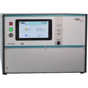
PG 6-364: HV Pulse Generator
The high-voltage impulse generator PG 6-364 generates standard impulse voltages with waveforms 1.2/50 µs and 10/700 µs. The Output voltage is adjustable between 0.2 kV and 6 kV. The polarity of the output voltage is selectable. Positive, negative or alternating polarity of the output voltage can be preselected. The generator is designed for dielectric testing of components and systems as well as testing of the electromagnetic compatibility of electronic systems and devices acc. to CCITT K17/K20/K22, ITU-T/K44, IEC 61000-4-5, VDE 0847.
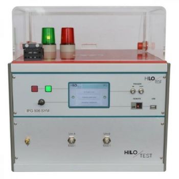
IPG 506 SYM: FRONT-CHOPPED-WAVE, 3-Pole DUT
The front-chopped-wave generator IPG 506 is used for measuring dc spark-over voltage and impulse spark-over voltage of over-voltage protectors according to CCITT / ITU-T, K12. DC spark-over voltage: A linearly rising voltage, rate of rise 100 V/s up to 640 V, simultaneous plus and minus, is connected to the device under test. The spark-over voltage of these two simultaneous impulses is measured and shown in the display. Impulse spark-over voltage: A linearly rising impulse voltage, simultaneous plus, and minus, rate of rise 100 V/µs up to 5000 V/µs, open loop amplitude 5000 V, is connected to the device under test. The spark-over voltage is measured by use of a peak detector. The results of these two simultaneous impulses are shown on the display. The picture is shown with PA 503 Option.
IPG 620/ IPG 1050/ IPG 1272 6kV, 10kV, 12kV
HV - Impulse generators IPG 620, IPG 1050 and IPG 1272 create standard impulse voltages with waveform 1.2 / 50 µs acc. to IEC 60. The generators simulate surges caused by switching of inductive loads, power system switching, lightning strokes, etc. They are designed for testing of impulse dielectric strength of components, insulation, air-and surface flash-over gaps as well as for testing surge immunity of devices and systems acc. to CCITT - K22, ITU-T-K44. Picture: incl. option PA503
PG 5-200 / PG 10-1000, High Voltage Pulse Generator, 10/700µs, 5/350µs, 1.2/50µs
The high-voltage pulse generator PG 5-200/ 10-1000 creates standard impulse voltages with waveforms 1.2/50 µs and 10/700 µs. It is designed for dielectric testing of components and systems as well as testing of the electromagnetic compatibility of electronic systems and devices acc. to CCITT-K17/K20/K22, ITU-T/K44, IEC 61000-4-5 etc. They are designed for testing of impulse dielectric strength of components, insulation, air-and surface flash-over gaps as well as for testing surge immunity of devices and systems acc. to CCITT - K22, ITU-T-K44. Picture: incl. option PA503
PG 12 - 1440, High Voltage Pulse Generator, 10/700µs, 1.2/50µs, 12kV
The high-voltage impulse generator PG 12-1440 standard impulse voltages with waveforms 1.2/50 µs or 10/700 µs. The output voltage is adjustable between 0.5 kV and 12 kV. The polarity of the output voltage is selectable. Positive, negative or alternating polarity of the output voltage can be preselected.
PG 14 - 1960, High Voltage Pulse Generator, 10/700µs, 0.5/700µs, 14kV
The high-voltage impulse generator PG 14-1960 generates standard impulse voltages with waveforms 10/700 µs. The output waveform can be switched to 0.5/700µs wave. Output voltage is adjustable between 0.2 kV and 14 kV. The polarity of the output voltage is selectable. Positive, negative or alternating polarity of the output voltage can be preselected.
PG 20 - 4000, High Voltage Pulse Generator, 10/700µs, 5/320µs, 20kV
The high-voltage impulse generator PG 20-4000 generates standard impulse voltages with waveform 10/700 µs. The output voltage is adjustable between 1 kV and 20 kV. The polarity of the output voltage is selectable, positive or negative.
PG 4-641, Impulse voltage, 3600 V
HV - Impulse generator PG 4-641 creates standard voltage and current pulses with a waveform 10 / 160 µs. The output voltage is adjustable up to 3600 V, the maximum short circuit current amplitude is 480 A peak. Positive or negative polarity of output voltage can be selected. A built-in voltage divider 1000:1 allows monitoring of the impulse output waveform during testing. The short circuit current wave can be monitored by the use of the built-in shunt.

