Products
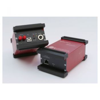
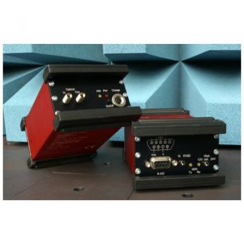
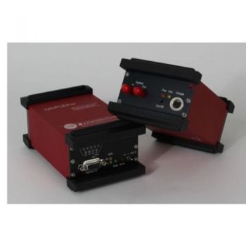
opto1394 This system is used for the optical transmission of IEEE1394/Firewire-signals and can transmit data rates of up to 400 Mbit/s (800 Mbit/s at 1394b). The transmitter system consists of two similar transceivers supplied by batteries and a duplex-62,5/125µm-multimode optical cable. Due to its insensitivity against strong electromagnetic fields, the opto1394 is fit for tests of electromagnetic compatibility in EMC-test chambers, TEM-cells, and striplines. The system can also be used for the fail-proof transmission of signals across long distances.
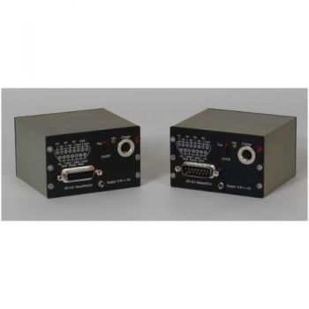
The optoSPI-HS system can be used for the bidirectional optical transmission of SPI signals with transmission rates of up to 1Mbit/s. It consists of two battery supplied transceivers connected to each other with an optical fiber. With the optical transmission of the shielded case and the external filter, the system is well equipped for EMI and EME tests.
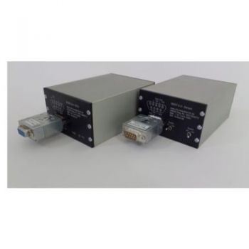
The optoSENT system was developed for the transmission of asynchronous SENT signals (Single Edge Nibble Transfer) and exists in two different versions.
The optoSENT system was developed for the transmission of asynchronous SENT signals (Single Edge Nibble Transfer) aThis system is used for the optical transmission of PSI5-signals and allows the transmission in both directions with a sampling rate of 50 MS/s. It consists of a transceiver, supplied by batteries, for the connection of a sensor, a simplex-62,5/125µm-multimode optical cable, and a receiver with internal batteries as well.nd exists in two different versions.
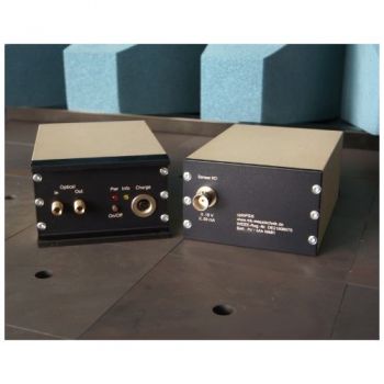
The optoK system can be used for the optical transmission of K-Line signals with transmission rates of more than 30kbit/s at supply voltages of up to 24V. It consists of two identical battery supplied transceivers connected to each other with an optical fiber. With the optical transmission and the shielded case, the system is well equipped for EMI and EME tests.
This system is used for the optical transmission of Flexray-signals and allows the transmission in both directions with a sampling rate of 10 MBit/s. It consists of two identical transceivers, supplied by batteries, and a simplex-62,5/125µm-multimode optical cable (1-fiber-version available on demand).
An electromagnetic reverberation chamber is a multifunctional EMC (Electromagnetic Compatibility) test facility for commercial, military, automotive testing, and other electromagnetic investigations. Also known as reverb chamber (RVC) or mode-stirred chamber (MSC) or, Vibrating intrinsic reverberation chamber (VRC). Compared to other measuring methods like EMC test in anechoic chambers or OATS (Open Area Test Sites), GTEM-cells offer some significant advantages for the testing of small and medium-sized EUT´s (Equipment Under Test) up to a frequency range of 20 GHz. Quick turn arounds of the EUT, as well as numerous testing variations, are easy and fast to handle. Switching from emission to immunity testing requires only simple adjustments from receiver input to the amplifier output.
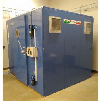
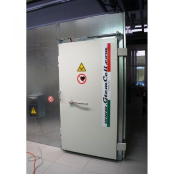
GTEMCELL Ltda shielded chambers are built up as modular construction. Due to individual modules, any size of the chamber can be realized. Big chambers may require an outer supporting structure or alternatively, the shielding material can be attached directly to the building. Panels are manufactured of 2,0 mm thickness hot galvanized sheet steel double bordered.
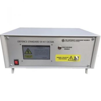
The Conformity Assessment Business Model DCS06 Test Generator has been designed to operate with its complementary injection clamp to fully meet the pulse requirements of DCS06 when tested into a 5? load. It operates from an intuitive touch screen interface and has full phase synchronization up to 800 Hz input frequency with 1-degree steps. It has been designed with future revisions of the test standard in mind.
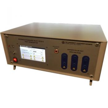
The Conformity Assessment Business Model DCS12 Test Generator meets all the DCS12 wave verification parameters for testing DC, single and three-phase equipment, that is source impedance and verification of damping and frequency when measured into a 10 Ω load. Output amplitude is software adjustable with permanent memory, should re-alignment be needed during calibration.
- There are three fixed outputs: 600 V, 750 V, and 2500 V
- 15.9 kHz ±10 %
- 10.9 kHz ±10 %

