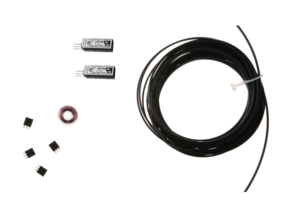
Langer LIN 100 Set | Optical LIN Bus Transmission
LIN | Bidirectional optical transmission | 8 to 15 V master; 8 to 30 V slave
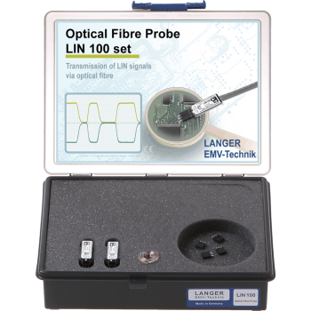
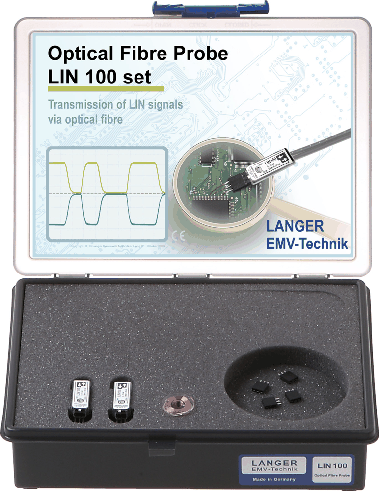
LIN 100 Set supports isolated bus connections for EMC testing. Up to 20 m fiber limit. Includes Double 10 m optical fiber. See the specifications for the individual module supply and operating conditions.
MARKETS:
CATEGORIES:
TEST STANDARDS:
Select Options/Sizes:

LIN 100 - Absolute EMC Datasheet
SPECIFICATIONS
LIN 100 Set | Optical LIN Bus Transmission
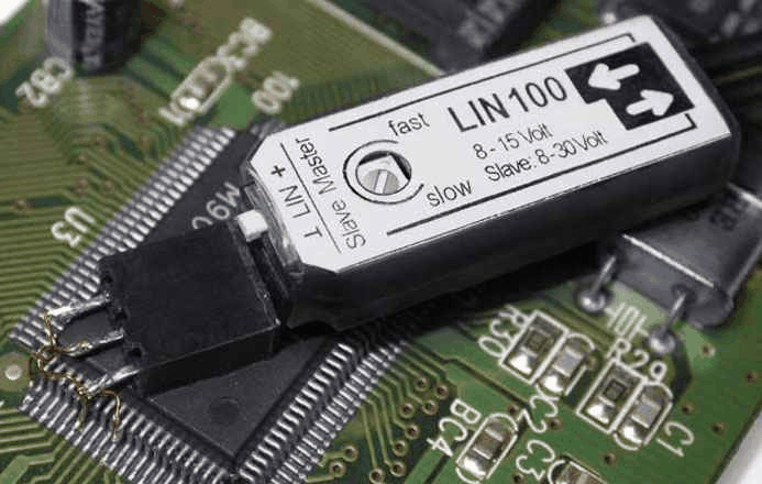
Transmit LIN communication bidirectionally through fiber with two compact LIN 100 probes. Configure the supply and master/slave connection to match the bus under test.
Choose a configuration
| Kit | Version | Signal bandwidth / rate | Included fiber |
|---|---|---|---|
 |
LIN 100 set | LIN bus | Double 10 m |
LIN 100 set specifications
| Parameter / component | Specification |
|---|---|
| LIN 100 Optical Fibre Probe | Component specifications below |
| Optical fibre connector | 2 x Ø 2.2 mm |
| Radiated immunity | > 200 V/m |
| Supply voltage (Master) | 8 - 15 V (Master) |
| Supply voltage (Slave) | 8 - 30 V (Slave) |
| Current input | max. 45 mA |
| Max. optical fibre length | 20 m |
LIN 100 set included components
| Photo | Included item | Qty. |
|---|---|---|
 |
LIN 100, Optical Fiber Probe | 2x |
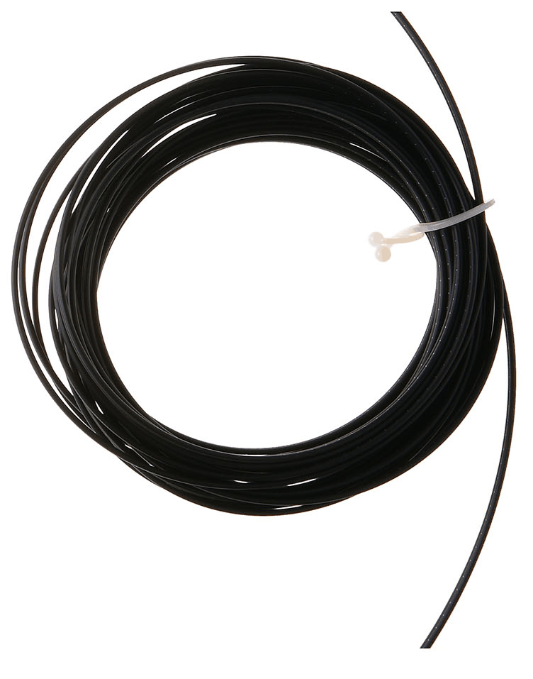 |
LWL double 10 m, Optical Fiber, Double 10 m | 1x |
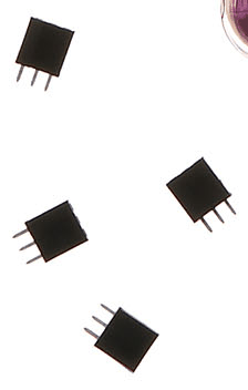  |
LIN 100 acc, Accessories | 1x |
|
A5 case, System case | 1x |
| LIN 100 m, LIN 100 Set User Manual | 1x |
LIN 100 set application and kit pictures


Connect the optical measurement path
Connect the sensor at the DUT, route the optical fiber to the receiver, and connect the receiver to the measuring instrument. Provide the specified supply separately at each end. Keep the installed fiber length within the model-specific limit. Choose the sensor voltage range and channel count before configuring the test.
Optical signal transmission for EMC testing
Datasheets
Compare all Langer optical signal transmission sets
| Kit | Model | Signal | Channels / direction | Bandwidth / data rate | Sampling / function | Supported fiber length | Included fiber |
|---|---|---|---|---|---|---|---|
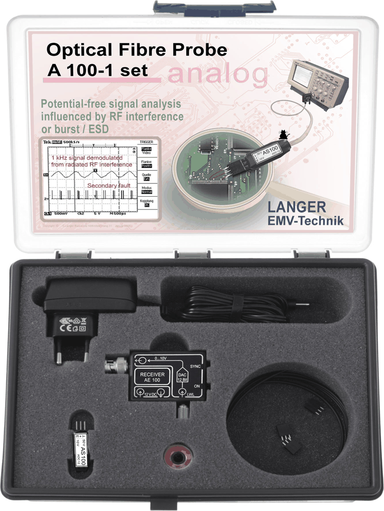 |
A100-1 set | Analog | 1 | DC to 25 kHz | 125 ksps / 12 bit | 1 to 20 m | 1.5 m |
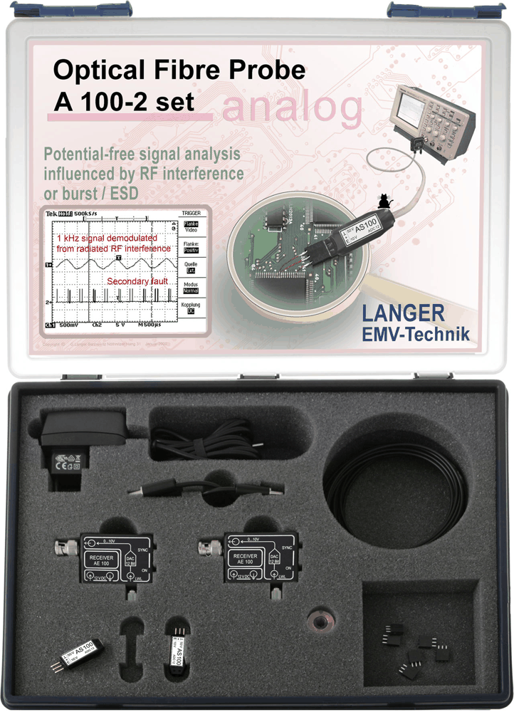 |
A100-2 set | Analog | 2 | DC to 25 kHz | 125 ksps / 12 bit | 1 to 20 m | 2 x 6 m |
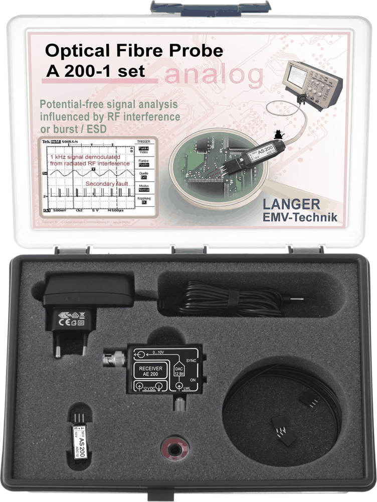 |
A200-1 set | Analog | 1 | DC to 500 kHz | 3 Msps / 12 bit | 1 to 20 m | 1.5 m |
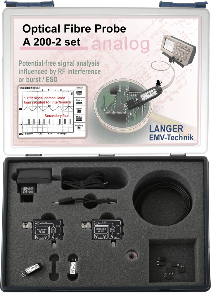 |
A200-2 set | Analog | 2 | DC to 500 kHz | 3 Msps / 12 bit | 1 to 20 m | 2 x 6 m |
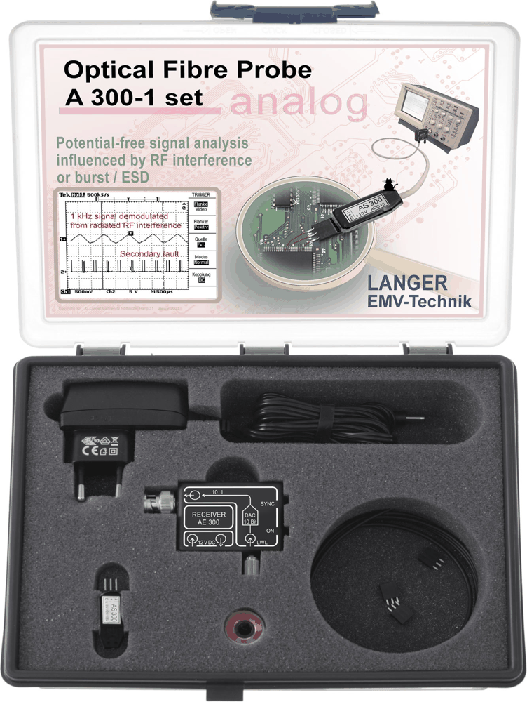 |
A300-1 set | Analog | 1 | DC to 5 MHz | 12.5 Msps / 10 bit | 1 to 20 m | 1.5 m |
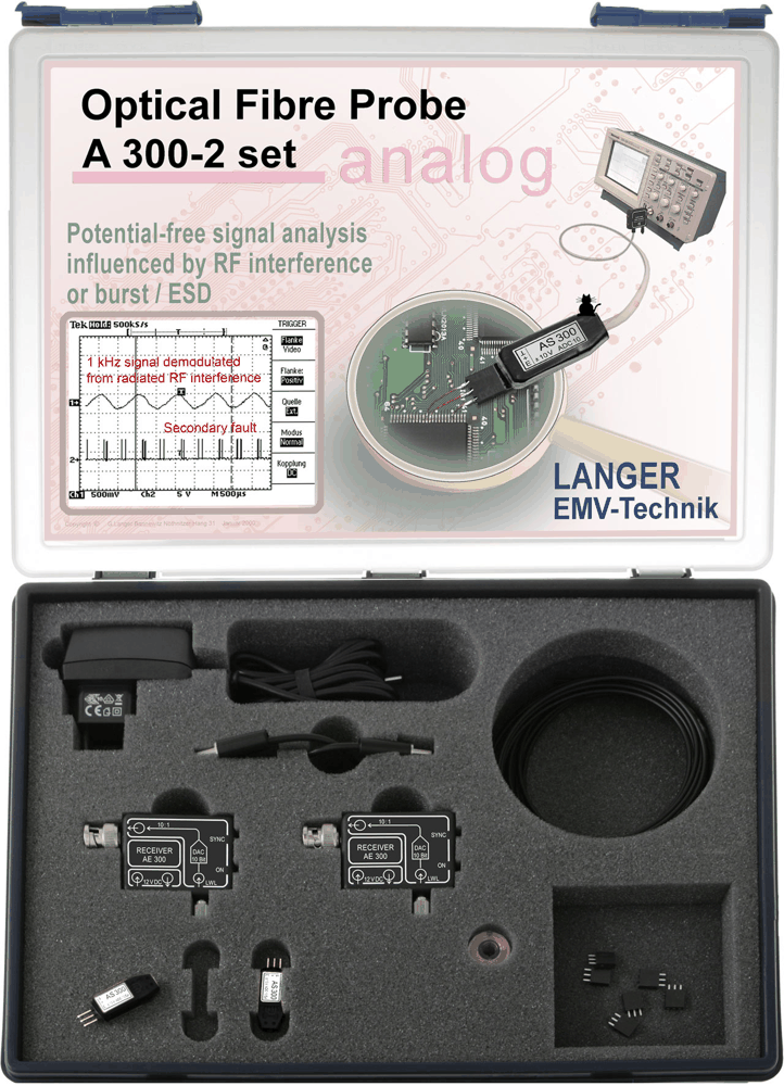 |
A300-2 set | Analog | 2 | DC to 5 MHz | 12.5 Msps / 10 bit | 1 to 20 m | 2 x 6 m |
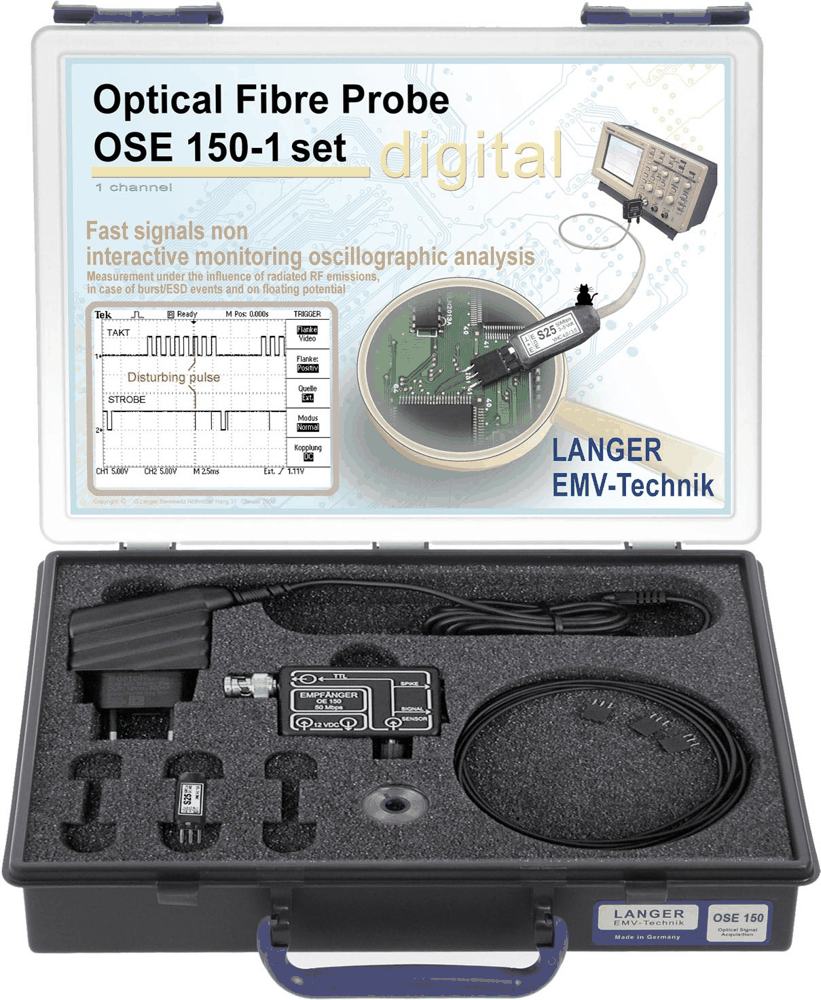 |
OSE 150-1 set | Digital | 1 | DC to 50 Mbps | Logic transmission | 1 to 20 m | 1.5 m |
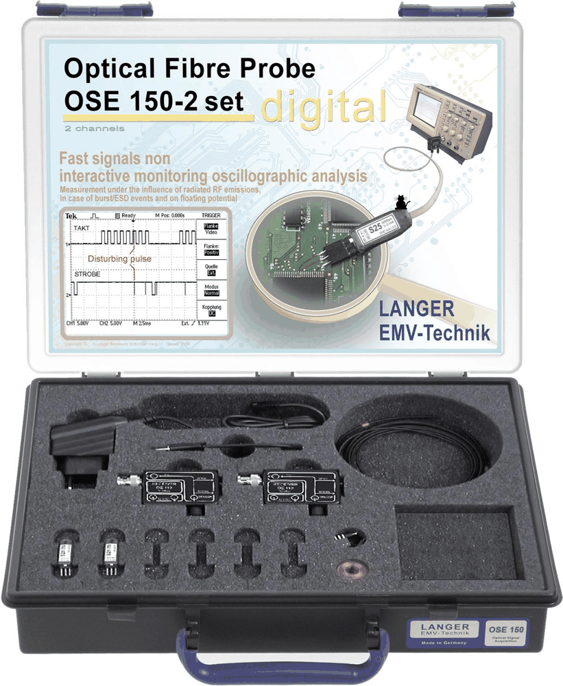 |
OSE 150-2 set | Digital | 2 | DC to 50 Mbps | Logic transmission | 1 to 20 m | 2 x 6 m |
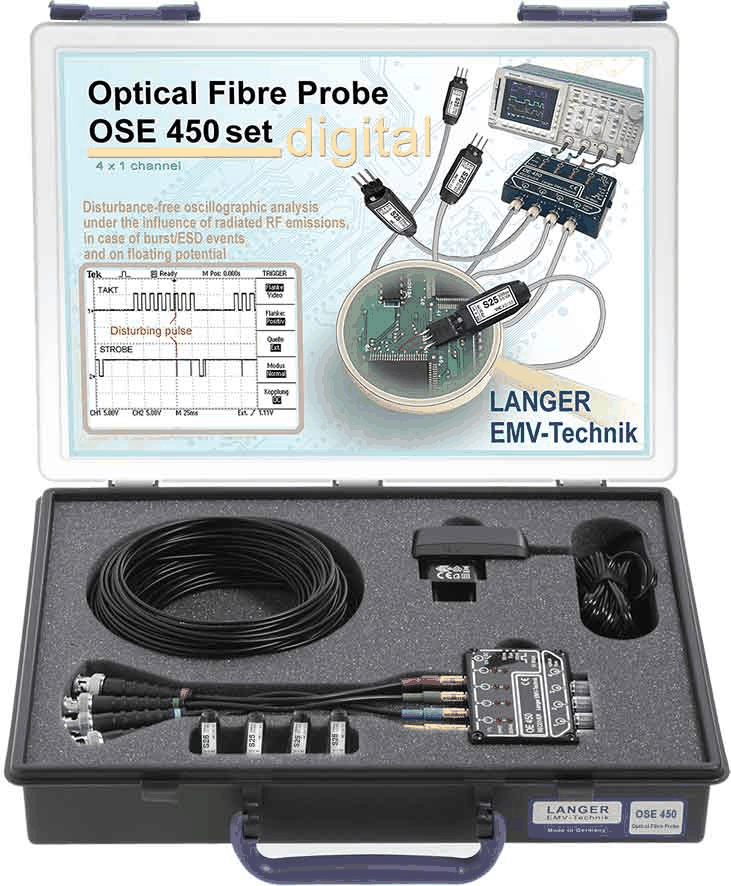 |
OSE 450 set | Digital | 4 | DC to 50 Mbps | Logic transmission | See receiver / sensor configuration | 4 x 6 m |
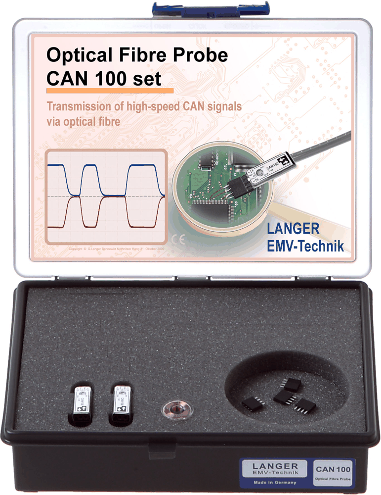 |
CAN 100 set | CAN | Bidirectional | Up to 1 Mbit/s | High-speed CAN | 10 m maximum; 6 m at 1 Mbit/s | Double 10 m |
|
LIN 100 set | LIN | Bidirectional | LIN bus | Master / slave | Up to 20 m | Double 10 m |
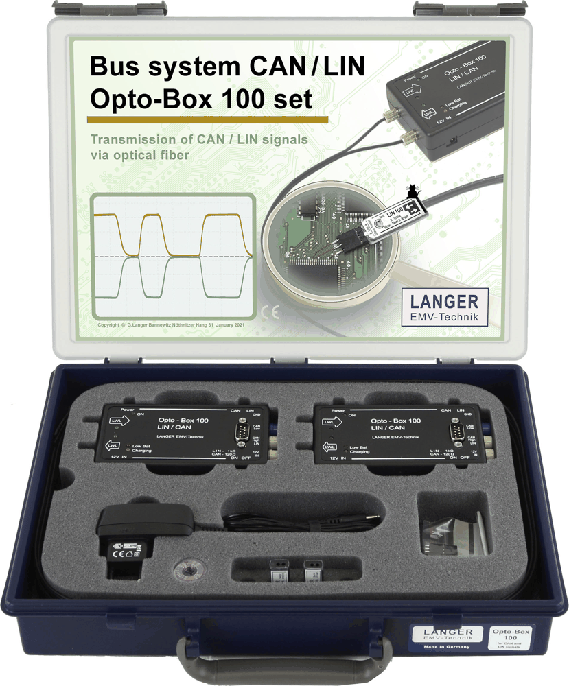 |
OB 100 set | CAN / LIN | Bidirectional | CAN / LIN selectable | 2 Opto-Boxes | 20 m; 6 m at 1 Mbit/s CAN | Double 10 m |
OTHER PRODUCTS IN THE SAME CATEGORY:
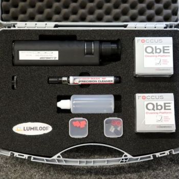
LS Fiber Connector Cleaning Kit
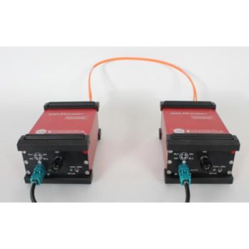
optoLAN 100Base-T1 BCM89811, Fiber-optic Link Automotive Ethernet signals
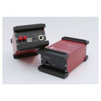
optoLAN-100 MBit/s, Fiber-optic Link Ethernet signals
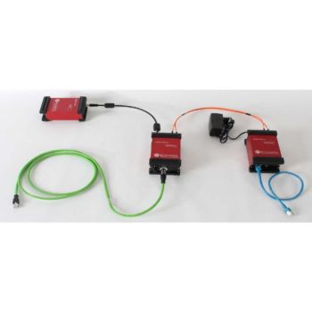
optoLAN 100/1000Base-TX, 1 GBit/s, Fiber-optic Link Ethernet signals

optoUSB2.0 -VA6K, Fiber-optic Link for USB
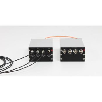
optoVIS-4 - transmission of visible light intensity
opto1394, Fiber-optic Link Firewire/IEEE 1394
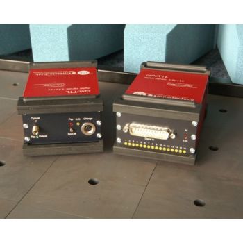
optoTTL 5-3-u, Fiber-optic Link for 3.5 & 5 V TTL signals
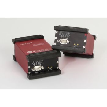
optoUART, Fiber-optic Link for UART Signals

optoUSB2.0, Fiber-optic Link for USB

optoTMDS-AV, Fiber-optic Link for HDMI signals

optoTTL 12-5-u, Fiber-optic Link for 5V & 12V TTL signals

optoUSB3.0, Fiber-optic Link for USB 3.0
optoUSB3.2 Gen1x1, Fiber-optic Link for USB 3.2

optoRS422, Fiber-optic Link for RS422 signals
optoRS232-HS, Fiber-optic Link for RS232 signals
optoRS485, Fiber-optic Link for RS485 signals

optoTTL b-12, Fiber-optic Link for 16 Bidirectional 12V TTL signals
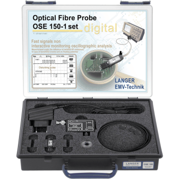
Langer OSE Digital Optical Fiber Probes | 1, 2 and 4 Channels