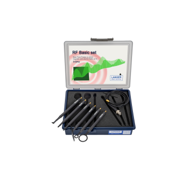
Langer Handheld Near-Field Probes
37 Langer handheld near-field probes | Passive electric and magnetic probes | Active MFA microprobes
Compare frequency coverage, probe size and orientation to locate EMI on PCB traces, IC pins, cables and microwave assemblies. Select a standalone probe or follow the kit links for complete sets and their individual options.
MARKETS:
CATEGORIES:
TEST STANDARDS:
Select Options/Sizes:

Langer XF-E 09s Datasheet
Langer LF-R 3 Datasheet
Langer LF-K 7 Datasheet
Langer XF E 04s Datasheet
Langer XF R 100-1 Datasheet
SPECIFICATIONS
Langer handheld near-field probe selection guide
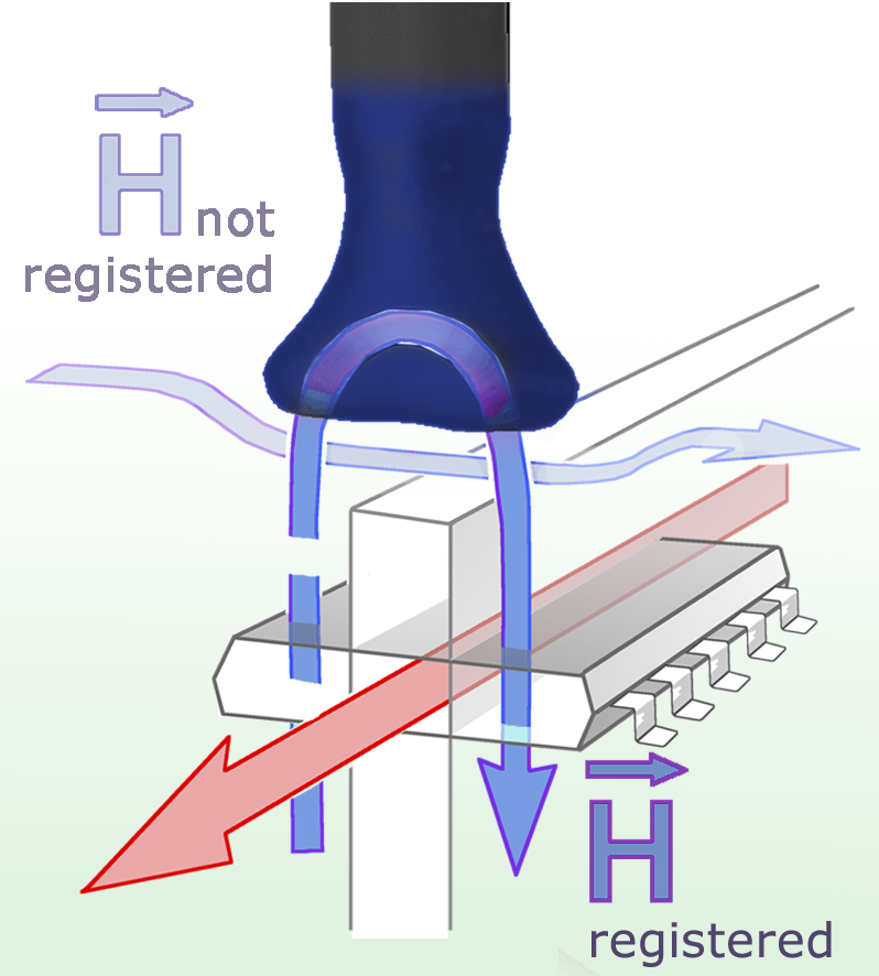
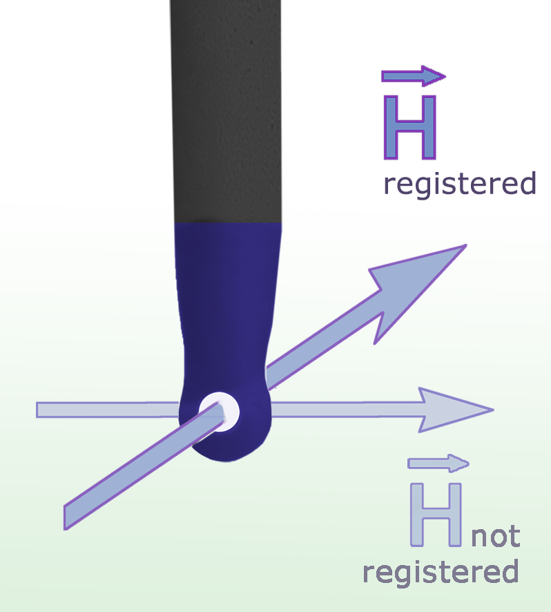
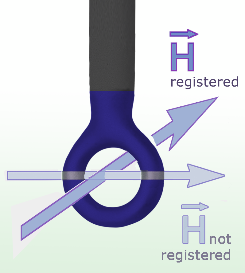
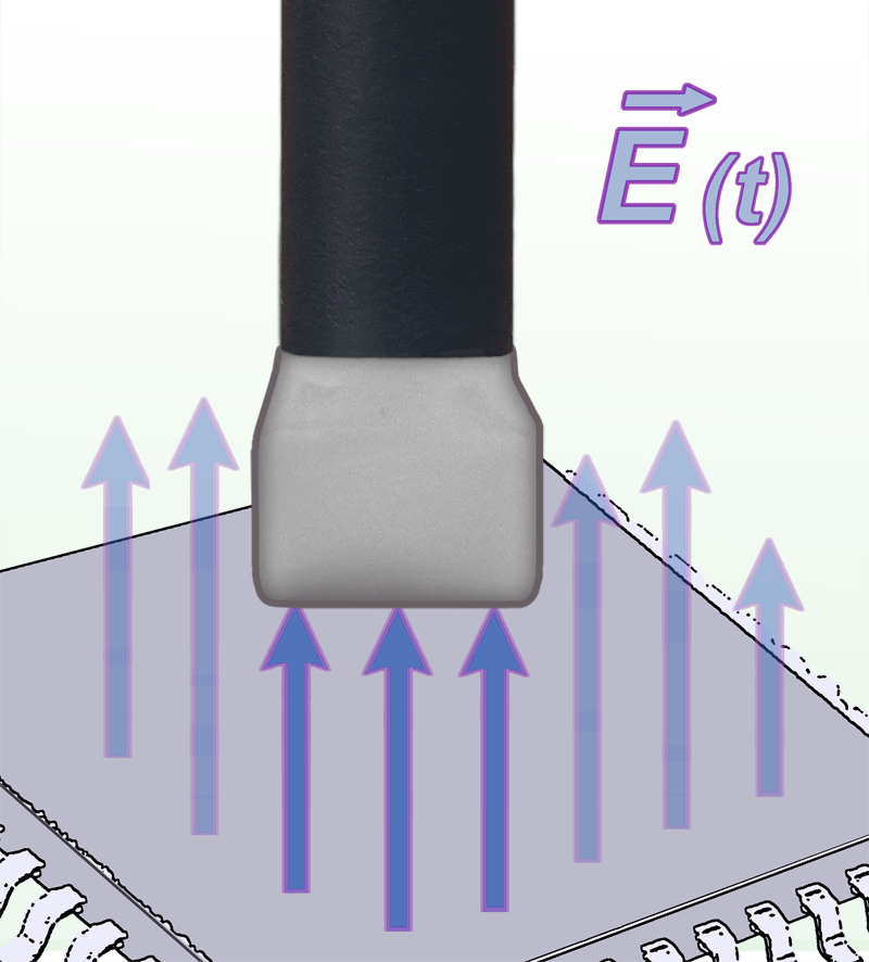
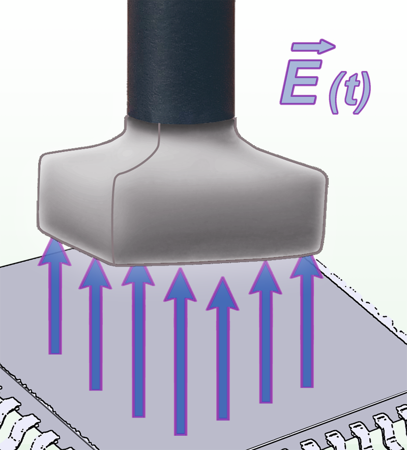
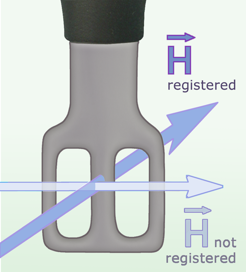
Start with a larger probe to survey the assembly, then use a smaller tip to pinpoint the source. Rotate magnetic loops to compare pickup. For electric-field measurements, aim the sensing face toward the source and keep the spacing consistent.
| Photo | Probe | Frequency range | Field / type | Size / resolution | Use and orientation | Available in these sets |
|---|---|---|---|---|---|---|
 |
LF-B 3 | 100 kHz to 50 MHz | H / passive | dia. approx. 4 mm Resolution approx. 2 mm |
Hold the shaft upright so the angled coil can reach between components. | LF1 set |
 |
LF-K 7 | 100 kHz to 50 MHz | H / passive | approx. (6 x 10) mm Resolution approx. 5 mm |
Use the paired coils near conductors, connectors or edges where the field wraps around the structure. | Individual probe |
 |
LF-R 3 | 100 kHz to 50 MHz | H / passive | dia. approx. 3 mm Resolution approx. 1 mm |
Bring the small loop close to traces, decoupling components and IC pins. | Individual probe |
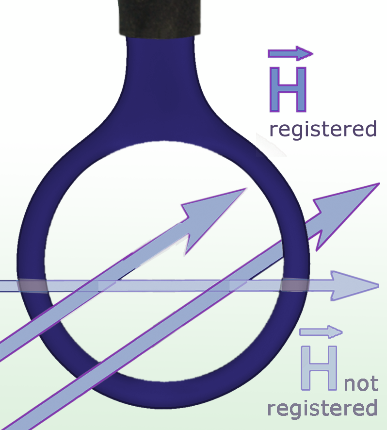 |
LF-R 400 | 100 kHz to 50 MHz | H / passive | dia. 25 mm | Survey the assembly with the large loop. Rotate it to maximize magnetic pickup. | LF1 set |
 |
LF-R 50 | 100 kHz to 50 MHz | H / passive | dia. approx. 10 mm | Survey nearby assemblies and cables before using a finer loop. | Individual probe |
 |
LF-U 2.5 | 100 kHz to 50 MHz | H / passive | dia. approx. 4 mm Resolution approx. 0.5 mm |
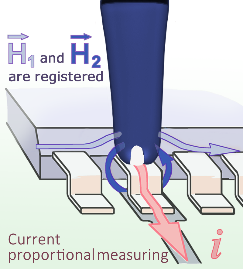
Place the narrow active gap over a trace or IC pin. | LF1 set |
 |
LF-U 5 | 100 kHz to 50 MHz | H / passive | approx. (6 x 6) mm Resolution approx. 5 mm |
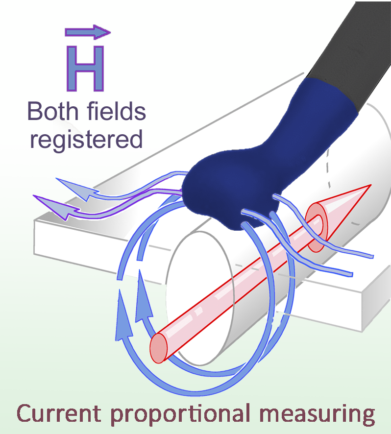
Position the wider U-shaped opening over broad traces, cables and connectors. | LF1 set |
 |
RF-B 0.3-3 | 30 MHz to 3 GHz | H / passive | dia. approx. 2 mm Resolution < 1 mm |
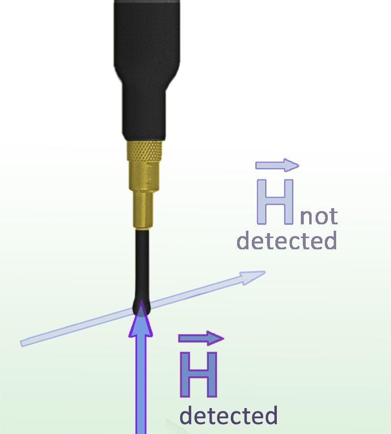
Use the angled coil with the shaft upright for close access between PCB components. | RF3 mini set |
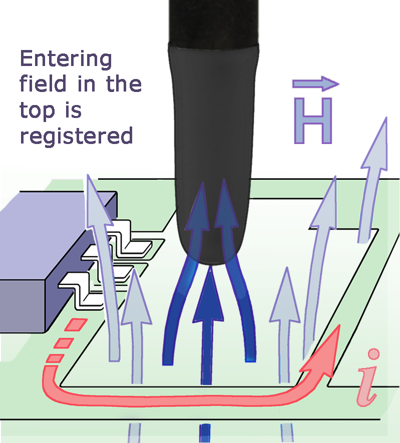 |
RF-B 3-2 | 30 MHz to 3 GHz | H / passive | dia. approx. 4 mm Resolution approx. 2 mm |
Use the angled coil with the shaft upright for close access between PCB components. | RF Basic set RF2 set |
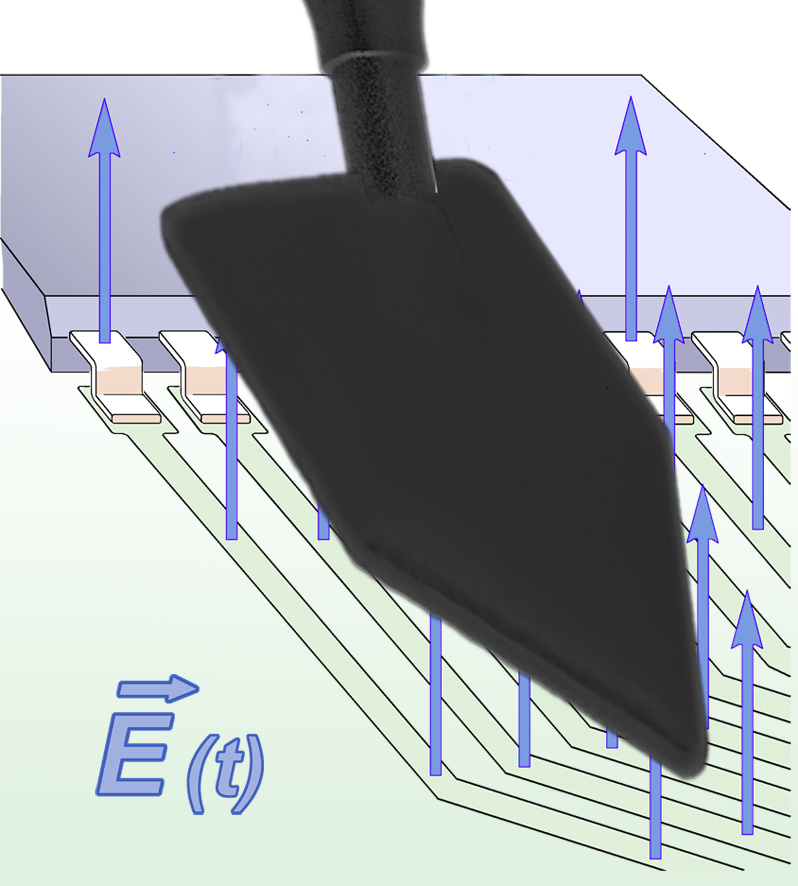 |
RF-E 02 | 30 MHz to 1.5 GHz | E / passive | approx. (23 x 53) mm | Face the broad underside electrode toward a bus or supply surface, typically at 1 to 2 cm. | RF Basic set RF4-E set |
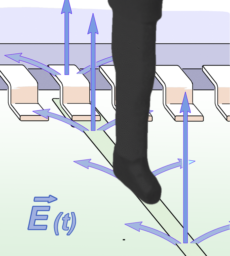 |
RF-E 05 | 30 MHz to 3 GHz | E / passive | approx. (1 x 8) mm Resolution approx. 0.6 mm |
Aim the fine underside electrode at clock traces or pins. Also suited to scanner use. | RF Basic set RF4-E set |
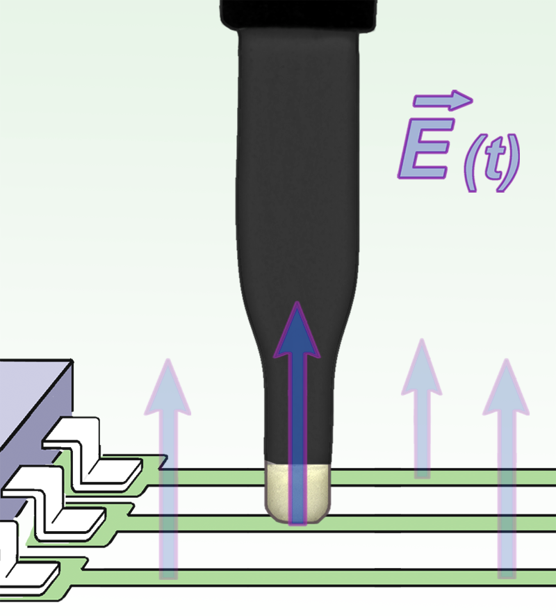 |
RF-E 10 | 30 MHz to 3 GHz | E / passive | approx. (0.5 x 2) mm Resolution approx. 0.2 mm |
Aim the narrow lower edge at individual pins or fine traces. | RF1 set |
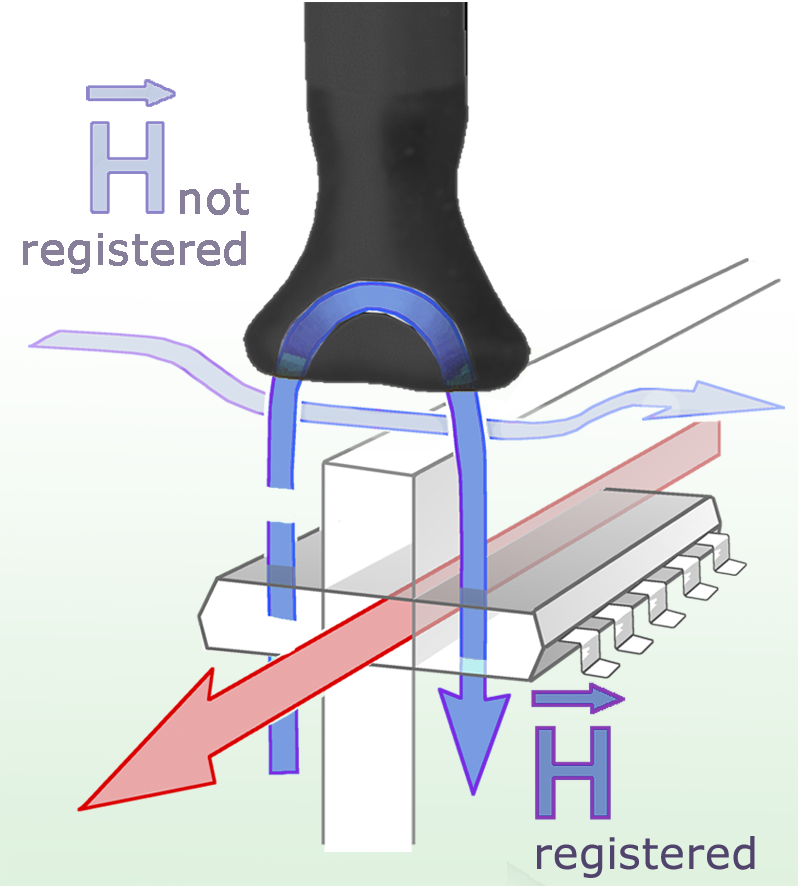 |
RF-K 7-4 | 30 MHz to 1 GHz | H / passive | approx. (6 x 10) mm Resolution approx. 5 mm |
Use the paired coils where the field wraps around a conductor, connector or edge. | RF1 set |
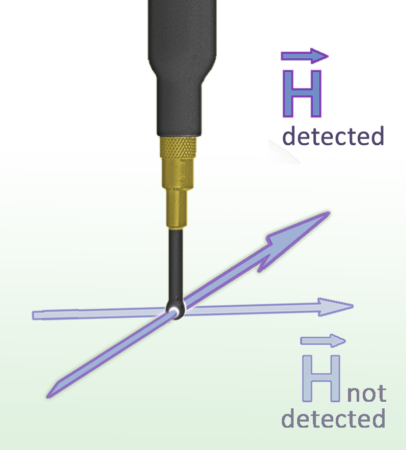 |
RF-R 0.3-3 | 30 MHz to 3 GHz | H / passive | dia. approx. 2 mm Resolution < 1 mm |
Use the miniature loop for sub-millimeter localization at small traces and pins. | RF3 mini set |
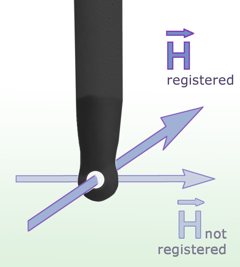 |
RF-R 3-2 | 30 MHz to 3 GHz | H / passive | dia. approx. 3 mm Resolution approx. 1 mm |
Bring the fine loop close to traces, IC pins or small components. Rotate to check field direction. | RF Basic set RF1 set |
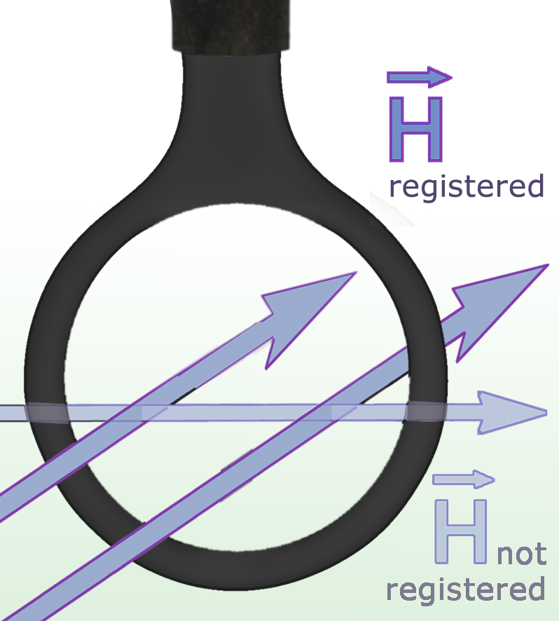 |
RF-R 400-1 | 30 MHz to 3 GHz | H / passive | dia. approx. 25 mm | Survey a broad area with the large loop before moving to a finer probe. | RF Basic set RF2 set |
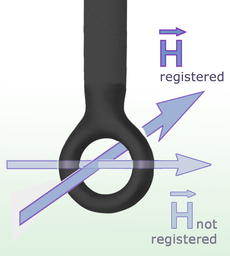 |
RF-R 50-1 | 30 MHz to 3 GHz | H / passive | dia. approx. 10 mm | Use the mid-size loop for closer surveys of assemblies or cables. | RF2 set |
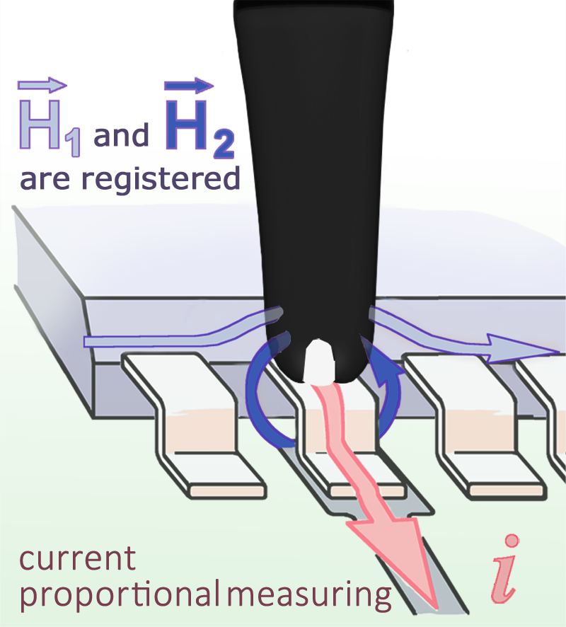 |
RF-U 2.5-2 | 30 MHz to 3 GHz | H / passive | dia. approx. 4 mm Resolution approx. 0.5 mm |
Align the narrow active gap over a trace or pin for selective RF current pickup. | RF Basic set RF1 set |
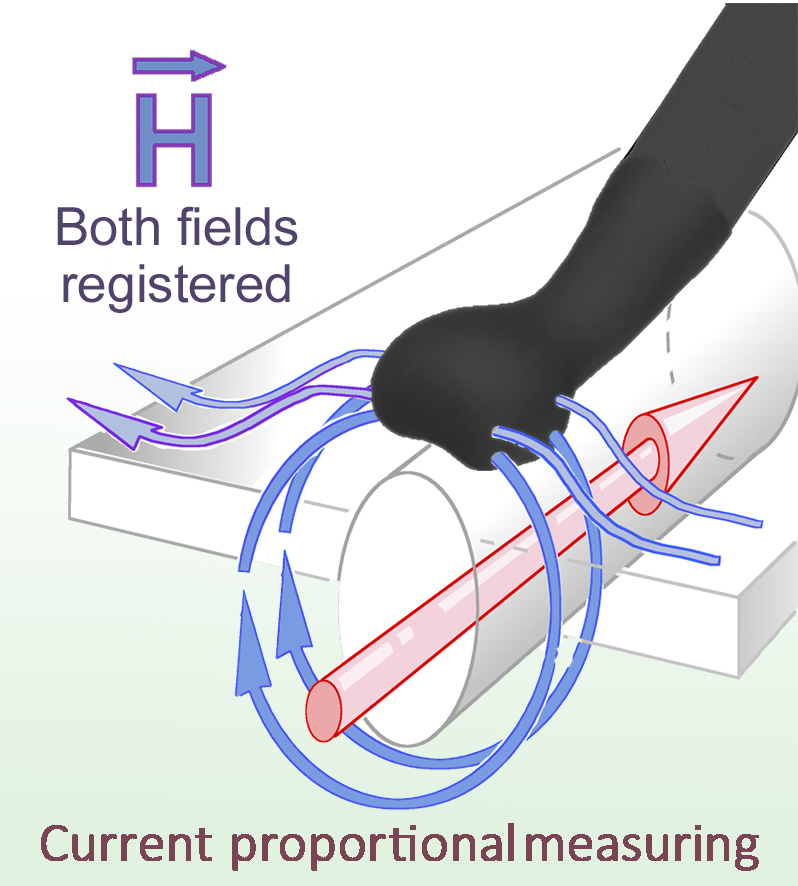 |
RF-U 5-2 | 30 MHz to 3 GHz | H / passive | approx. (6 x 6) mm Resolution approx. 5 mm |
Use the wider opening over broad conductors, cables or connectors. | RF2 set |
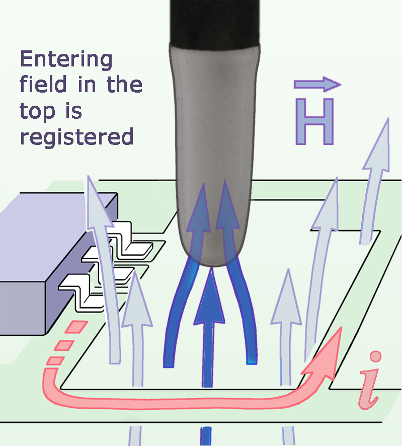 |
XF-B 3-1 | 30 MHz to 6 GHz | H / passive | dia. approx. 4 mm Resolution approx. 2 mm |
Use the angled coil with the shaft upright for close access between PCB components. | XF1 set |
 |
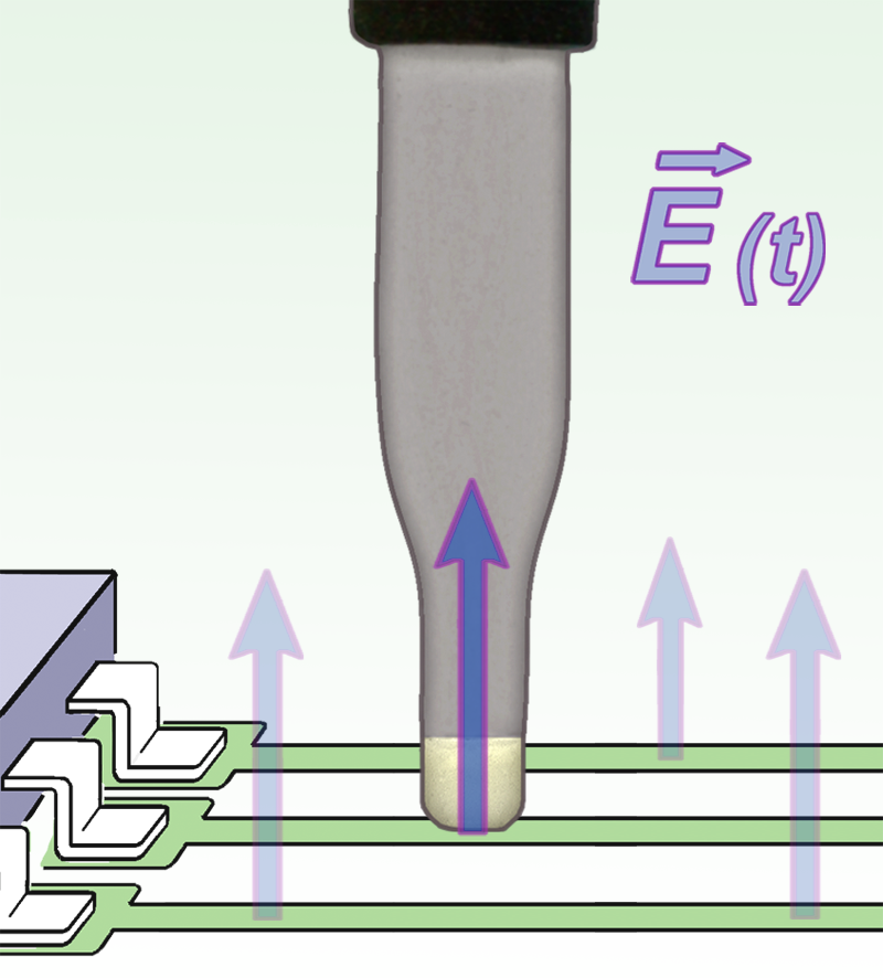
XF-E 04s | 30 MHz to 6 GHz | E / passive | approx. (5 x 5) mm | Face the small electrode toward the IC or trace at 0.5 to 10 mm. | Individual probe |
 |
XF-E 09s | 30 MHz to 6 GHz | E / passive | approx. (10 x 10) mm | Face the larger electrode toward the IC at 0.5 to 10 mm. | Individual probe |
 |
XF-E 10 | 30 MHz to 6 GHz | E / passive | approx. (0.5 x 2) mm Resolution approx. 0.2 mm |
Align the narrow electrode with a trace or pin for fine E-field localization. | XF1 set |
 |
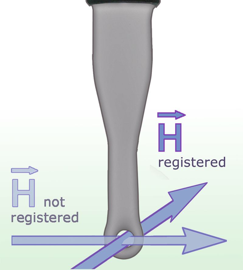
XF-R 100-1 | 30 MHz to 6 GHz | H / passive | approx. (10x10) mm Resolution dia. approx. 10 mm |
Use the mid-size head for localized magnetic surveys. Rotate to find the strongest coupling. | Individual probe |
 |
XF-R 3-1 | 30 MHz to 6 GHz | H / passive | dia. approx. 3 mm Resolution approx. 1 mm |
Bring the fine loop close to traces, IC pins or small components. Rotate to check field direction. | XF1 set |
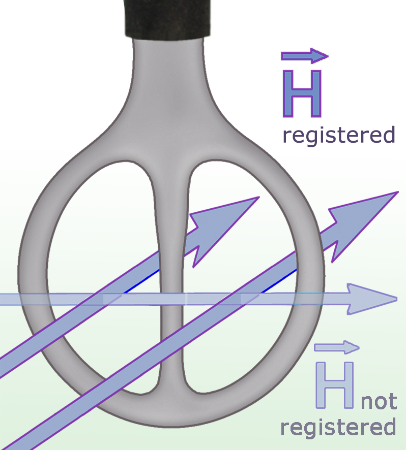 |
XF-R 400-1 | 30 MHz to 6 GHz | H / passive | dia. approx. 25 mm | Survey a broad area with the large loop before moving to a finer probe. | XF1 set |
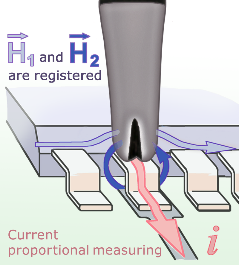 |
XF-U 2.5-1 | 30 MHz to 6 GHz | H / passive | dia. approx. 4 mm Resolution approx. 0.5 mm |
Align the narrow active gap over a trace or pin for selective RF current pickup. | XF1 set |
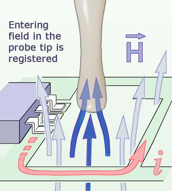 |
SX-B 3-1 | 1 GHz to 10 GHz | H / passive | dia. approx. 4 mm Resolution approx. 2 mm |
Use the angled coil with the shaft upright for close access between PCB components. | SX1 set |
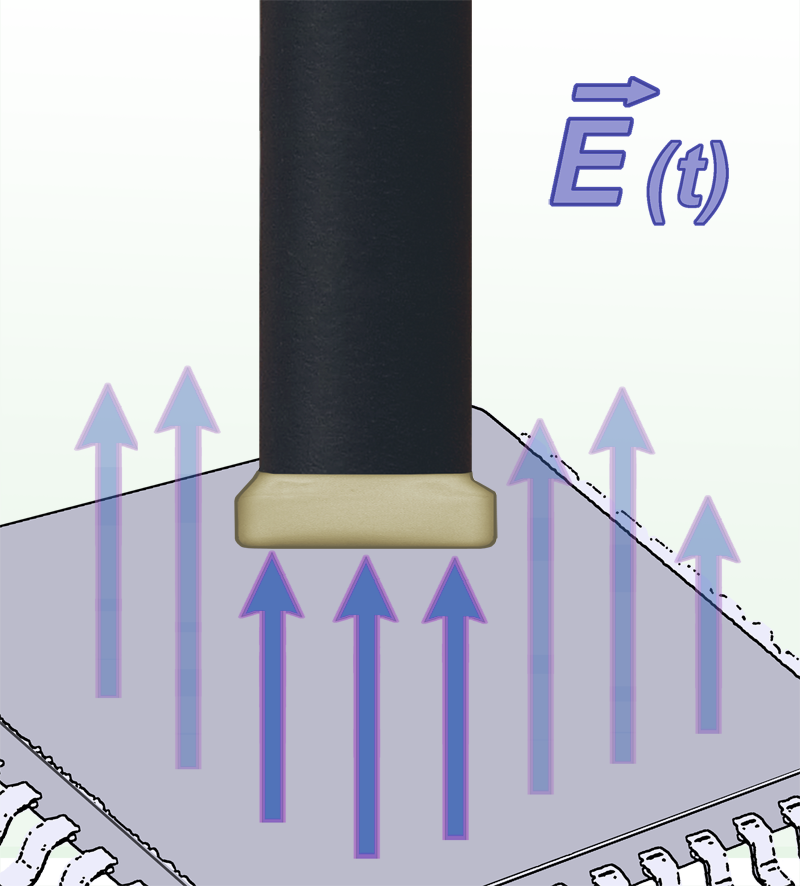 |
SX-E 03 | 1 GHz to 10 GHz | E / passive | approx. (4 x 4) mm | Aim the underside electrode toward the trace or component. | SX1 set |
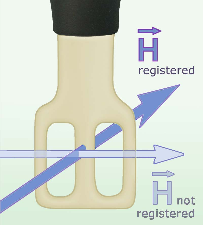 |
SX-R 20-1 | 1 GHz to 20 GHz | H / passive | approx. 6x6 mm | Bring the compact magnetic head close to microwave traces or ICs and rotate to compare coupling. | SX-R 20-1 set |
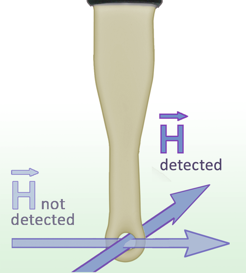 |
SX-R 3-1 | 1 GHz to 10 GHz | H / passive | dia. approx. 3 mm Resolution approx. 1 mm |
Bring the fine loop close to traces, IC pins or small components. Rotate to check field direction. | SX1 set |
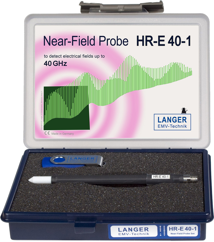 |
HR-E 40-1 | Up to 40 GHz | E / passive | 0.25 mm electrode diameter Resolution 0.2 mm |
Aim the small electrode toward the microwave trace. Keep standoff consistent. | HR1 set HR-E 40-1 set |
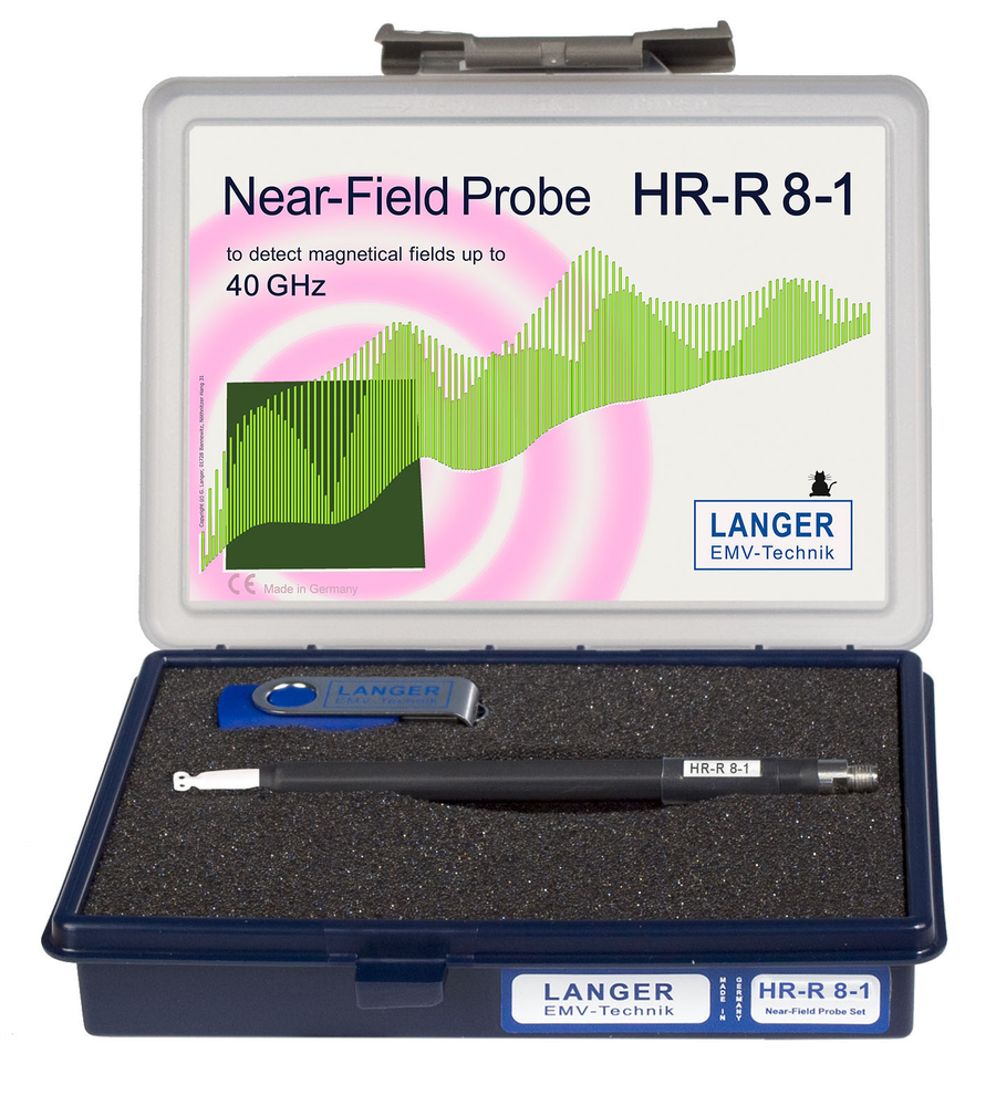 |
HR-R 8-1 | Up to 40 GHz | H / passive | 4 x 4 x 1 mm head | Bring the magnetic tip close to microwave traces or packages. Internal matching is 50 ohm. | HR1 set HR-R 8-1 set |
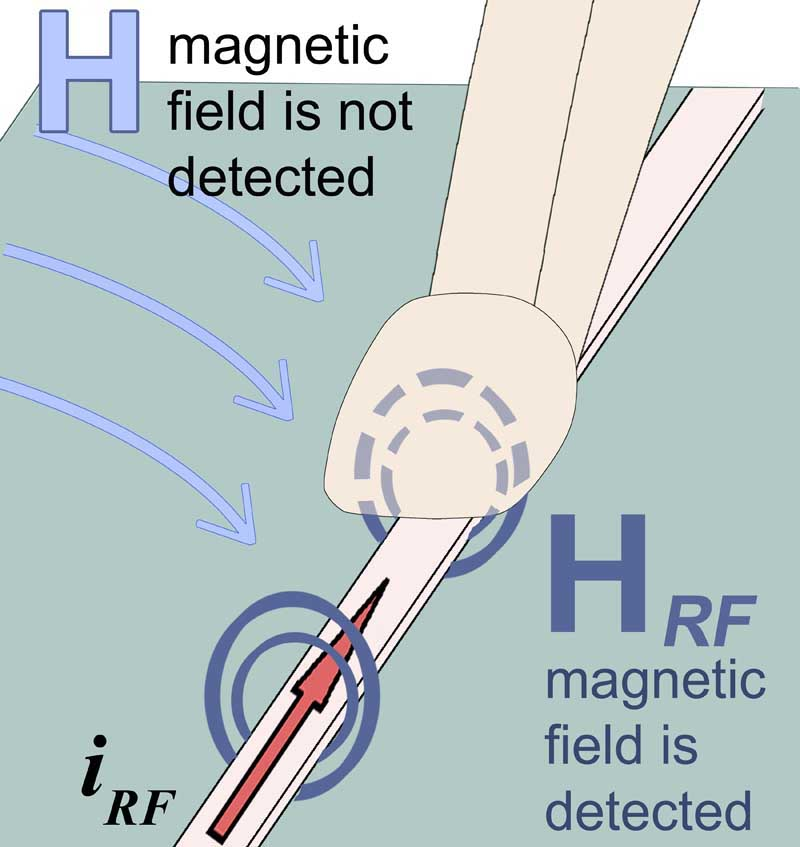 |
MFA-K 0.1-12 | 100 MHz to 6 GHz | H / active | Resolution 200 um | Center the shielded head over the conductor for selective RF current pickup. Power through the BT 706 bias tee. | MFA 01 set |
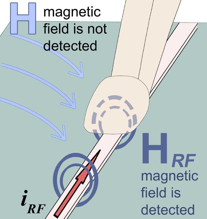 |
MFA-K 0.1-30 | 1 MHz to 1 GHz | H / active | Resolution 200 um | Center the shielded head over the conductor for selective RF current pickup. Power through the BT 706 bias tee. | MFA 02 set |
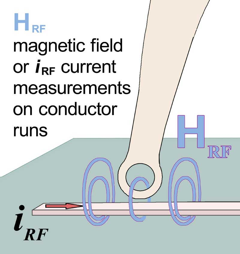 |
MFA-R 0.2-6 | 100 MHz to 6 GHz | H / active | Resolution 300 um | Place the active miniature head near pins or SMD components and rotate to compare magnetic pickup. Use the BT 706 bias tee. | MFA 01 set |
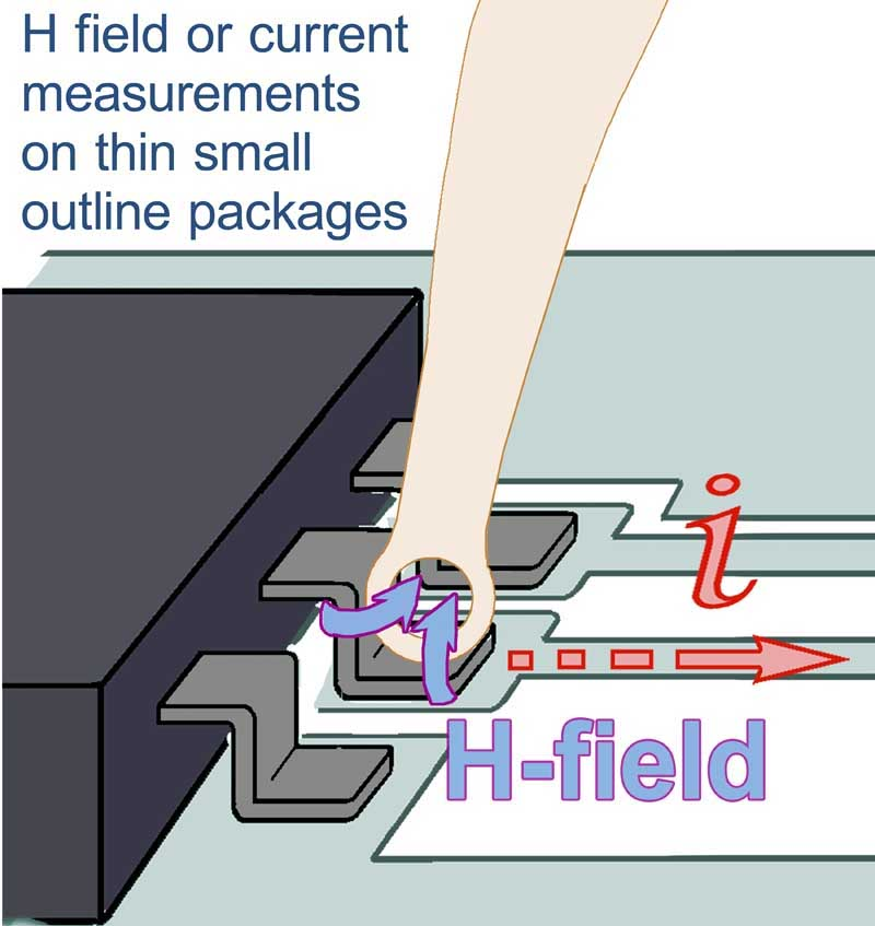 |
MFA-R 0.2-75 | 1 MHz to 1 GHz | H / active | Resolution 300 um | Place the active miniature head near pins or SMD components and rotate to compare magnetic pickup. Use the BT 706 bias tee. | MFA 01 set MFA 02 set |
Measurement setup
Use a suitable spectrum analyzer or oscilloscope with a 50 ohm input and cables rated for the measurement frequency. Active MFA probes require the BT 706 bias tee and a suitable power supply. Physical tip size and spatial resolution are listed separately where Langer specifies both.
OTHER PRODUCTS IN THE SAME CATEGORY:
EMProbe-DBM-E6 — 6-Axis Robotic Near-Field EMI Diagnostics on the Bench
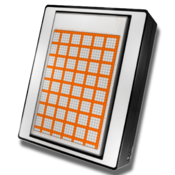
EMScanner+: 150 kHz- 6 GHz, w/ Real-Time Spectrum Analyzer, EMC desktop scanner
EMScannerR+: 150 kHz- 6 GHz, w/ Real-Time Spectrum Analyzer, EMC desktop scanner
EMScanner: 150 kHz- 8 GHz, 3.5mm Resolution, EMC desktop scanner
EMScannerR: 150 kHz- 8 GHz, 0.06mm resolution, EMC desktop scanner
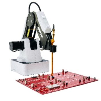
EMProbe: 9kHz- 18 GHz, 0.2mm resolution, EMC robotic scanner
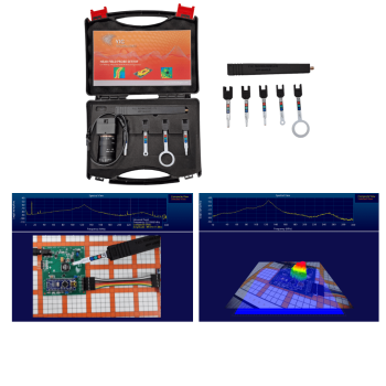
NFPKIT, EM Near Field Probe Kit w/Camera & Software

FS-SET 7100 B, 9 kHz - 1 GHz, Active Nearfield Probe Set
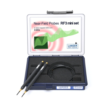
Langer RF3 mini Set | 30 MHz to 3 GHz Near-Field Probes
Langer Handheld Near-Field Probes
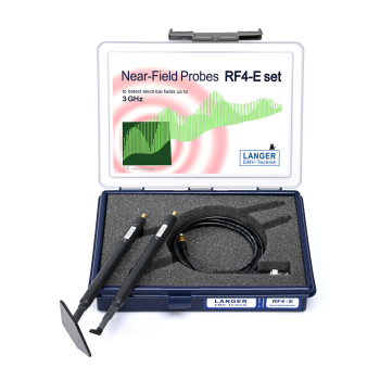
Langer RF4-E Set | 30 MHz to 3 GHz Near-Field Probes
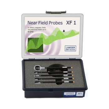
Langer XF1 Set | 30 MHz to 6 GHz Near-Field Probes
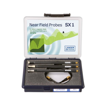
Langer SX1 Set | 1 GHz to 10 GHz Near-Field Probes
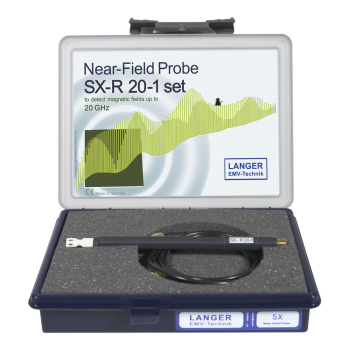
Langer SX-R 20-1 Set | 1 GHz to 20 GHz Near-Field Probes
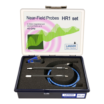
Langer HR1 Set | Up to 40 GHz Near-Field Probes
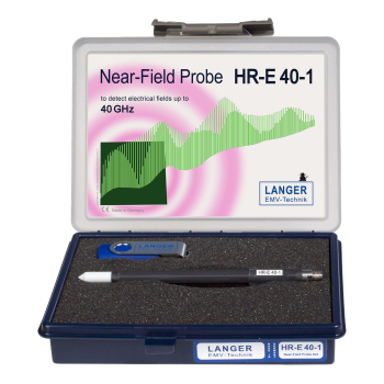
Langer HR-E 40-1 Set | Up to 40 GHz Near-Field Probes
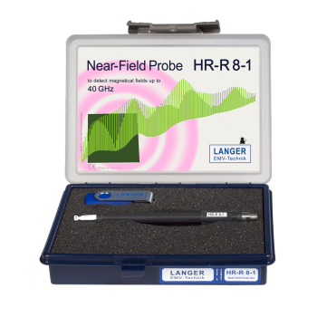
Langer HR-R 8-1 Set | Up to 40 GHz Near-Field Probes
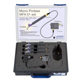
Langer MFA 01 Set | 1 MHz to 6 GHz Near-Field Probes
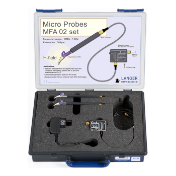
Langer MFA 02 Set | 1 MHz to 1 GHz Near-Field Probes