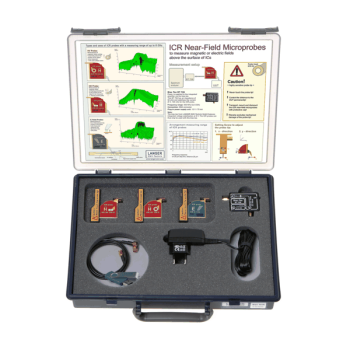
Langer ICR Near-Field Microprobe Selection Guide
Scanner-mounted Langer ICR microprobes | 16 H-field models, one E-field model and the configurable ICR 03 kit
Compare frequency coverage, coil or electrode geometry, and spatial resolution to select a probe for IC and fine PCB emissions mapping.
MARKETS:
CATEGORIES:
TEST STANDARDS:
SPECIFICATIONS
Choose the sensing orientation first, then compare frequency coverage and spatial resolution. HH probes use a horizontal magnetic coil. HV probes use a vertical magnetic coil. E150 uses a horizontal electrode for electric-field scans. The ICR 03 kit lets you select three ICR probes for a shared setup.
Horizontal-coil magnetic microprobes (HH)
| Kit photo | Model/ Set | Frequency range | Field/ Orientation | Coil ID or electrode size | Spatial resolution | Use |
|---|---|---|---|---|---|---|
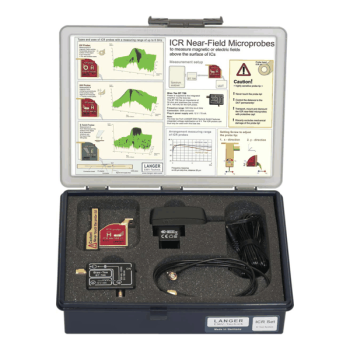 |
ICR HH100-27 set | 1.5 MHz to 6 GHz | H-field / horizontal coil | 100 um | 70 um | Measure the magnetic component normal to the board with the coil parallel to the surface. Langer lists higher gain at the lower end of the frequency range for this variant. |
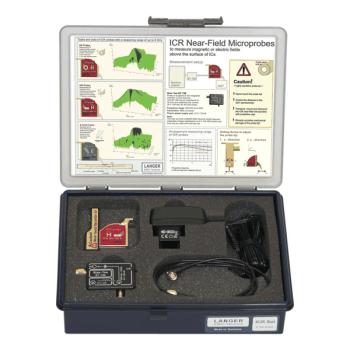 |
ICR HH100-6 set | 2.5 MHz to 6 GHz | H-field / horizontal coil | 100 um | 70 um | Measure the magnetic component normal to the board with the coil parallel to the surface. |
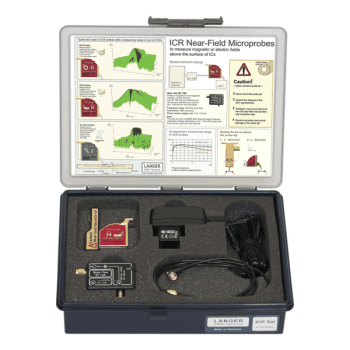 |
ICR HH150-27 set | 1.5 MHz to 6 GHz | H-field / horizontal coil | 150 um | 100 um | Measure the magnetic component normal to the board with the coil parallel to the surface. Langer lists higher gain at the lower end of the frequency range for this variant. |
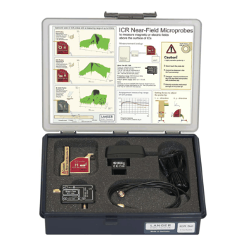 |
ICR HH150-6 set | 2.5 MHz to 6 GHz | H-field / horizontal coil | 150 um | 100 um | Measure the magnetic component normal to the board with the coil parallel to the surface. |
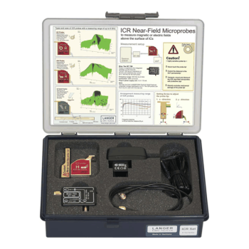 |
ICR HH250-6 set | 2.5 MHz to 6 GHz | H-field / horizontal coil | 250 um | 150 um | Measure the magnetic component normal to the board with the coil parallel to the surface. |
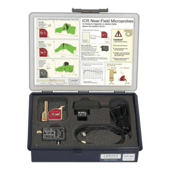 |
ICR HH250-75 set | 500 kHz to 2 GHz | H-field / horizontal coil | 250 um | 150 um | Measure the magnetic component normal to the board with the coil parallel to the surface. Langer lists higher gain at the lower end of the frequency range for this variant. |
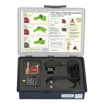 |
ICR HH500-6 set | 2 MHz to 6 GHz | H-field / horizontal coil | 500 um | 300 um | Measure the magnetic component normal to the board with the coil parallel to the surface. |
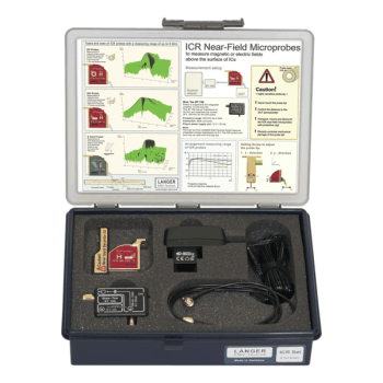 |
ICR HH500-75 set | 200 kHz to 1 GHz | H-field / horizontal coil | 500 um | 300 um | Measure the magnetic component normal to the board with the coil parallel to the surface. Langer lists higher gain at the lower end of the frequency range for this variant. |
Vertical-coil magnetic microprobes (HV)
| Kit photo | Model/ Set | Frequency range | Field/ Orientation | Coil ID or electrode size | Spatial resolution | Use |
|---|---|---|---|---|---|---|
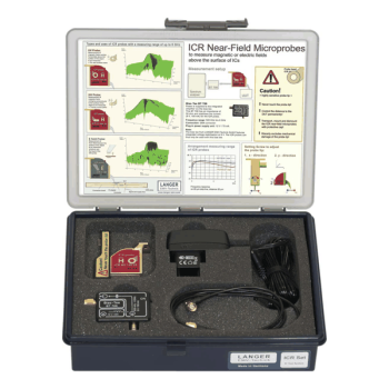 |
ICR HV100-27 set | 1.5 MHz to 6 GHz | H-field / vertical coil | 100 um | 60 um | Measure a magnetic component parallel to the board. Rotate about the scan axis to compare directions. Langer lists higher gain at the lower end of the frequency range for this variant. |
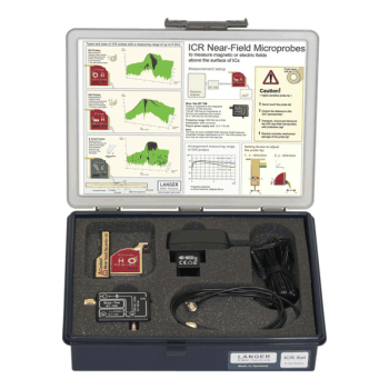 |
ICR HV100-6 set | 2.5 MHz to 6 GHz | H-field / vertical coil | 100 um | 60 um | Measure a magnetic component parallel to the board. Rotate about the scan axis to compare directions. |
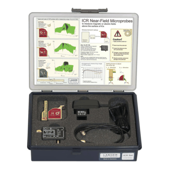 |
ICR HV150-27 set | 1.5 MHz to 6 GHz | H-field / vertical coil | 150 um | 80 um | Measure a magnetic component parallel to the board. Rotate about the scan axis to compare directions. Langer lists higher gain at the lower end of the frequency range for this variant. |
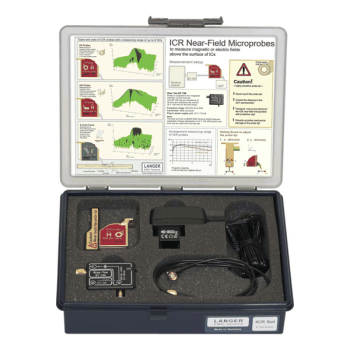 |
ICR HV150-6 set | 2.5 MHz to 6 GHz | H-field / vertical coil | 150 um | 80 um | Measure a magnetic component parallel to the board. Rotate about the scan axis to compare directions. |
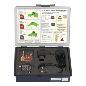 |
ICR HV250-6 set | 2.5 MHz to 6 GHz | H-field / vertical coil | 250 um | 110 um | Measure a magnetic component parallel to the board. Rotate about the scan axis to compare directions. |
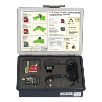 |
ICR HV250-75 set | 500 kHz to 2 GHz | H-field / vertical coil | 250 um | 110 um | Measure a magnetic component parallel to the board. Rotate about the scan axis to compare directions. Langer lists higher gain at the lower end of the frequency range for this variant. |
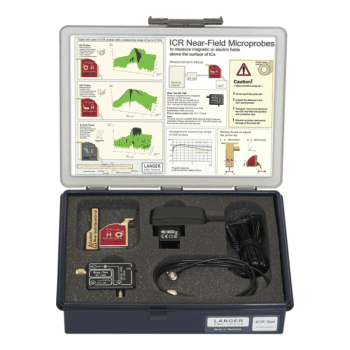 |
ICR HV500-6 set | 2 MHz to 6 GHz | H-field / vertical coil | 500 um | 300 um | Measure a magnetic component parallel to the board. Rotate about the scan axis to compare directions. |
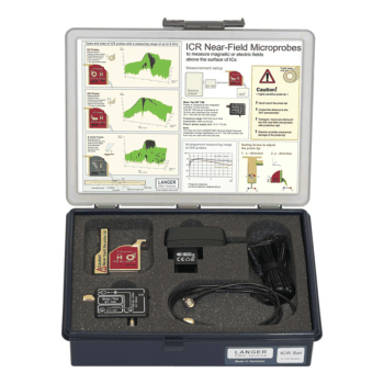 |
ICR HV500-75 set | 200 kHz to 1 GHz | H-field / vertical coil | 500 um | 300 um | Measure a magnetic component parallel to the board. Rotate about the scan axis to compare directions. Langer lists higher gain at the lower end of the frequency range for this variant. |
Electric-field probe and configurable kit
| Kit photo | Model/ Set | Frequency range | Field/ Orientation | Coil ID or electrode size | Spatial resolution | Use |
|---|---|---|---|---|---|---|
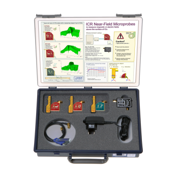 |
ICR 03 set | Depends on the three selected probes | Choose H-field or E-field | Depends on probe choice | Depends on probe choice | Select three ICR probes with a shared bias tee and cable. |
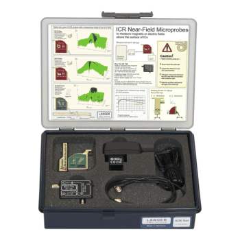 |
ICR E150 set | 7 MHz to 3 GHz | E-field / horizontal electrode | (150 x 35) um | 65 um | Map electric near fields on IC packages and pins. |
Measurement setup
Use a compatible positioning system and receiver or spectrum analyzer. The BT 706 bias tee powers the integrated preamplifier. Use the correction data supplied with the probe, and keep scan height and orientation consistent when comparing designs.
OTHER PRODUCTS IN THE SAME CATEGORY:
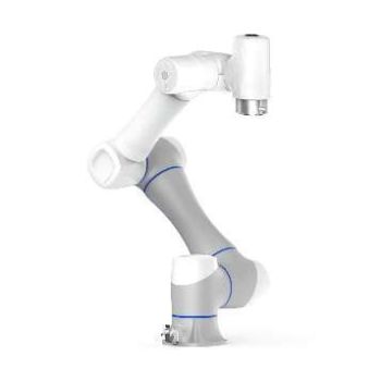
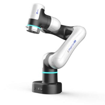
EMProbe-DBM-E6 — 6-Axis Robotic Near-Field EMI Diagnostics on the Bench
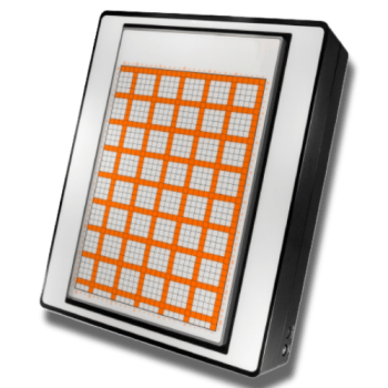
EMScanner+: 150 kHz- 6 GHz, w/ Real-Time Spectrum Analyzer, EMC desktop scanner
EMScannerR+: 150 kHz- 6 GHz, w/ Real-Time Spectrum Analyzer, EMC desktop scanner
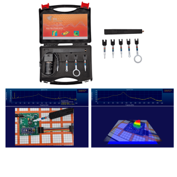
NFPKIT, EM Near Field Probe Kit w/Camera & Software
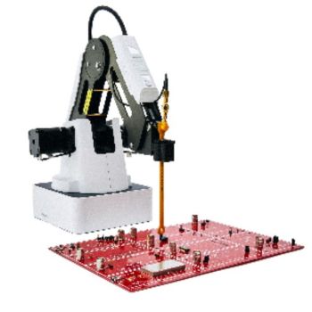
EMProbe: 9kHz- 18 GHz, 0.2mm resolution, EMC robotic scanner
EMScannerR: 150 kHz- 8 GHz, 0.06mm resolution, EMC desktop scanner
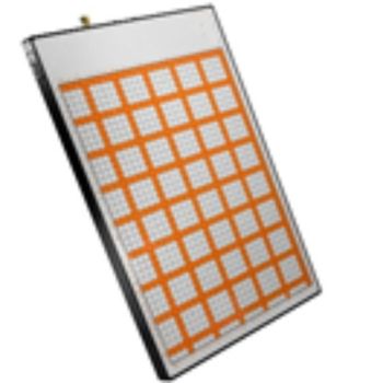
EMScanner: 150 kHz- 8 GHz, 3.5mm Resolution, EMC desktop scanner
Langer ICR Near-Field Microprobe Selection Guide
Langer Handheld Near-Field Probes Selection Guide

FS-SET 7100 B, 9 kHz - 1 GHz, Active Nearfield Probe Set
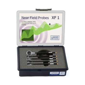
Langer XF1 Set | 30 MHz to 6 GHz Near-Field Probes

Langer ICR HH100-6 Set | 2.5 MHz to 6 GHz Near-Field Probes
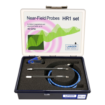
Langer HR1 Set | Up to 40 GHz Near-Field Probes
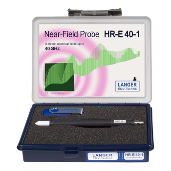
Langer HR-E 40-1 Set | Up to 40 GHz Near-Field Probes

Langer ICR HH100-27 Set | 1.5 MHz to 6 GHz Near-Field Probes
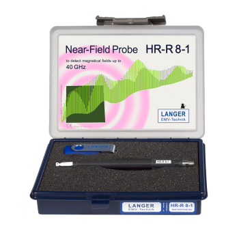
Langer HR-R 8-1 Set | Up to 40 GHz Near-Field Probes

Langer ICR E150 Set | 7 MHz to 3 GHz Near-Field Probes
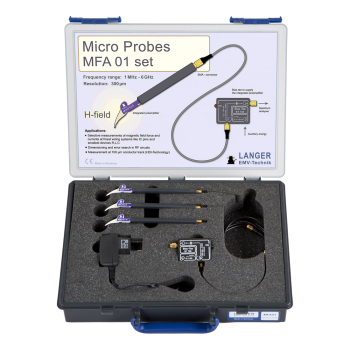
Langer MFA 01 Set | 1 MHz to 6 GHz Near-Field Probes
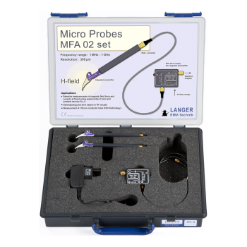
Langer MFA 02 Set | 1 MHz to 1 GHz Near-Field Probes