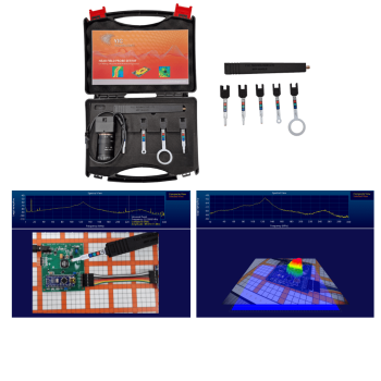


NFPKIT, EM Near Field Probe Kit w/Camera & Software
5 E/H-field probes | Camera tracking | Live EMI visualization
NFP Kit adds camera-based position tracking to handheld near-field measurements. EMViewer recognizes the probe and measurement location from visible markers, helping engineers map emission sources while moving the probe by hand. The kit combines five electric/magnetic probes, a camera, mounting arm and measurement software with your compatible spectrum analyzer.
PARTNER:
MARKETS:
CATEGORIES:
TEST STANDARDS:
Select Options/Sizes:

Data Sheet
Setup Guide
SPECIFICATIONS
NFP Kit - Camera-Tracked Near-Field Probes and EMViewer
5 E/H-field probes | Camera tracking | Live EMI visualization

Application and capabilities
NFP Kit adds camera-based position tracking to handheld near-field measurements. EMViewer recognizes the probe and measurement location from visible markers, helping engineers map emission sources while moving the probe by hand. The kit combines five electric/magnetic probes, a camera, mounting arm and measurement software with your compatible spectrum analyzer.
- Locate RF sources around components, traces, cables and assemblies.
- Compare before/after changes using consistent probe orientation, height and analyzer settings.
- Use EMViewer to connect measurement values with their location on the DUT.
Technical specifications
| Specification | Details |
|---|---|
| Measurement method | Handheld, camera-tracked |
| Spectrum analyzer | External instrument supported by EMViewer; 50-ohm RF input required for NFP Kit |
| Frequency coverage | Determined by selected probe, analyzer and RF path; dedicated robotic datasheets specify up to 14 GHz for supplied set, with E-field probe listed to 18 GHz |
| Scan area / workspace | Camera field of view / setup |
| Scan spacing / positioning | Manual positioning; tracking/setup dependent |
| Camera | USB mini camera; 5 MP; 5-50 mm varifocal lens; 10x optical zoom |
| Camera mounting | 11-inch adjustable support arm with clamp |
| Probe correction | Normalization/correction in EMViewer |
| Probe construction | Slim design with protective coating |
| RF cable | 18 GHz measured cable listed by manufacturer |
| Software modes | Spectral/spatial scans, live tracking and reporting |
| PC requirements in guide | Windows 10/11, x86-64; 2-core 1 GHz or faster CPU, 8 GB RAM, OpenGL 4.2, 200 MB installation plus 1 GB project storage |
Probe selection and frequency coverage
| Probe | Field | Published operating band |
|---|---|---|
| HXY 10A02 | Magnetic | 10 MHz-300 MHz |
| HXY 20A02 | Magnetic | 100 MHz-1.4 GHz |
| HZ 40A02 | Magnetic | 1-14 GHz |
| HXY 60A01 | Magnetic | 1-13 GHz |
| E 00A02 | Electric | 1.6-18 GHz in retained datasheets; current NFP Kit webpage states 1.6-14 GHz |
System components
Documented system components
- Five E/H-field probes
- Probe handle and tracking markers
- USB camera
- Adjustable camera support arm/clamp
- RF cable listed by manufacturer
- EMViewer license/support package as quoted
User-supplied or separately specified
- Compatible external spectrum analyzer and RF connection
- PC with the supported EMViewer release
- DUT power, mounting and access for the intended probe path
Measurement workflow
| Step | What the engineer does |
|---|---|
| 1. Configure | Choose the frequency band, analyzer settings and scan area; connect the DUT and measurement system. |
| 2. Locate | Run a spectral or spatial scan to identify frequencies and emission hot spots. |
| 3. Investigate | Refine the region, probe position or resolution while keeping the setup controlled. |
| 4. Compare | Repeat after a design change, compare results and retain maps and reports. |
Software and configuration
EMViewer links scan position with RF measurements. Available modes include spectral sweeps, spatial hot-spot maps and combined scans. Confirm the supported software release, analyzer driver, license and support term when configuring the system.
EMViewer software information | Spectrum-analyzer compatibility
Keep the probe markers and tip in focus and visible to the camera with suitable lighting. Tracking quality depends on setup; no numerical position accuracy is specified.
The retained probe datasheet lists E 00A02 to 18 GHz, while the current manufacturer kit page lists 14 GHz. Confirm the supplied probe version and correction file for the required band.
The retained probe datasheet lists E 00A02 to 18 GHz, while the current manufacturer kit page lists 14 GHz. Confirm the supplied probe version and correction file for the required band.
Datasheets and setup resources
Manufacturer product information
Compare Y.I.C. near-field scanning solutions
Choose the measurement method, analyzer configuration and workspace that fit your DUT. Select a product name or picture for its full details.
| Product | Method / best fit | RF coverage / analyzer | Scan area or workspace | Sampling / positioning |
|---|---|---|---|---|
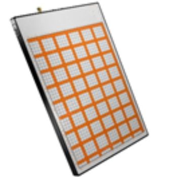 EMScanner |
Fixed H-field array Fast PCB overview and design comparisons |
150 kHz to 8 GHz External, compatible |
316 x 218 mm | 7.5 mm pitch; 3.75 mm effective |
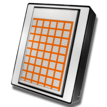 EMScannerR |
High-resolution array Dense PCB hot-spot detail |
150 kHz to 8 GHz External, compatible |
316 x 218 mm | 7.5 to 0.06 mm; 8 levels |
 EMScanner+ |
Fixed H-field array Fast PCB overview and design comparisons |
150 kHz to 6 GHz Internal BB60C |
316 x 218 mm | 7.5 mm pitch; 3.75 mm effective |
 EMScannerR+ |
High-resolution array Dense PCB hot-spot detail |
150 kHz to 6 GHz Internal BB60C |
316 x 218 mm | 7.5 to 0.06 mm; 8 levels |
NFP Kit |
Handheld, camera-tracked Interactive troubleshooting and flexible probing |
Probe/analyzer dependent; see probe table External, compatible |
Camera field of view / setup | Manual positioning; tracking/setup dependent |
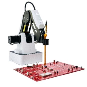 EMProbe |
Compact robotic arm Component-side and variable-height scans |
Probe/analyzer dependent; see probe table External, compatible |
300 mm radius, standard arm | 7.5 to 0.2 mm scan spacing |
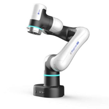 EMProbe DBM E6 |
6-axis robot Repeatable multi-angle scans |
Probe/analyzer dependent; see probe table External, compatible |
450 mm radius | 0.1 mm scan spacing; 0.01 mm repeatability |
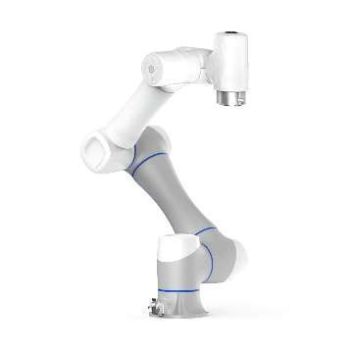 EMProbe CR5 |
Custom 6-axis robot Larger DUTs and custom fixtures |
Selected probes and analyzer External, compatible |
900 mm working-radius example; usable scan envelope customized | +/-0.02 mm robot repeatability; scan spacing specified per project |
Array spacing, effective resolution, robotic scan spacing and robot repeatability describe different properties. Probe systems do not have one continuous guaranteed frequency range independent of the selected probe and analyzer. CR5 values are a project example; final specifications are defined by quotation. Near-field diagnostics support EMC development and do not replace a formal emissions compliance test.
OTHER PRODUCTS IN THE SAME CATEGORY:
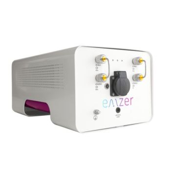
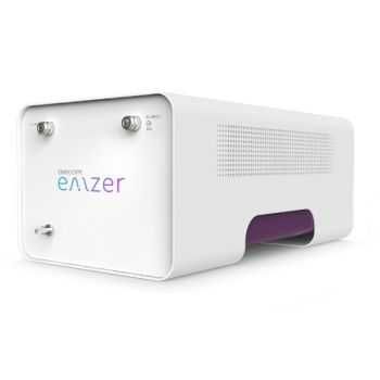
EMSCOPE-RX2, 9kHz - 110MHz, 2 channel Receiver
EMSCOPE-RX4, 9kHz - 110MHz, 4 channel Receiver for 3 phase
EMSCOPE Click Meter for CISPR 14-1

EMProbe CR5 - Custom Large-Reach Robotic EMI Scanning System

EMProbe-DBM-E6 — 6-Axis Robotic Near-Field EMI Diagnostics on the Bench

EMScanner+: 150 kHz- 6 GHz, w/ Real-Time Spectrum Analyzer, EMC desktop scanner
EMScannerR+: 150 kHz- 6 GHz, w/ Real-Time Spectrum Analyzer, EMC desktop scanner
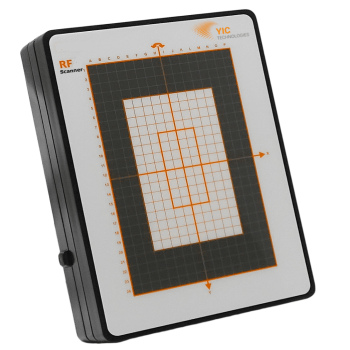
RFScanner, Antenna Pattern measurement, 300MHz - 6 GHz
NFPKIT, EM Near Field Probe Kit w/Camera & Software

EMProbe: 9kHz- 18 GHz, 0.2mm resolution, EMC robotic scanner
EMScannerR: 150 kHz- 8 GHz, 0.06mm resolution, EMC desktop scanner

EMScanner: 150 kHz- 8 GHz, 3.5mm Resolution, EMC desktop scanner
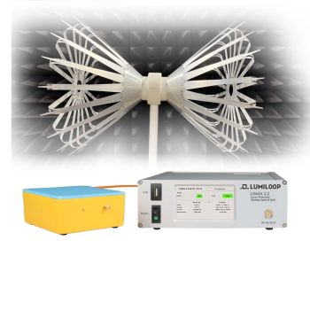
LSAOL 1.2 Laser-Powered Analog Optical Link
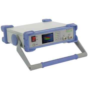
TBMR-110M DC - 110 MHz high speed EMI-Analyzer
eNFPKIT, Educational Kit EM Near Field Probe Kit w/Camera & Software
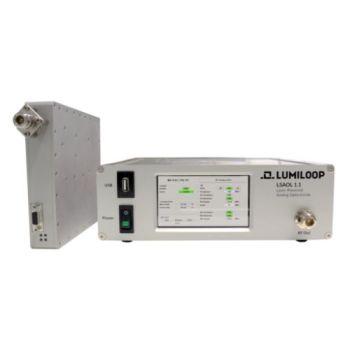
LSAOL 1.1, Laser Powered RF Link, 9kHz - 6GHz Discontinued
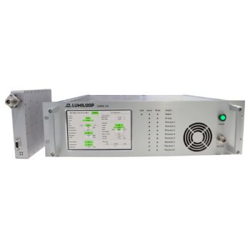
LSAOL 1.0, Laser Powered RF Link, Discontinued
EMSCOPE, 9kHz - 110MHz, 2 channel Receiver/LISN
EMSCOPE-RX4, 9kHz - 110MHz, 4 channel Receiver for 3 phase