Langer ESA1 Set | EMC Emission Development System
11 near-field probes | 100 kHz to 1 GHz line-current measurements | 20 dB preamplifier | Shielding tent + software
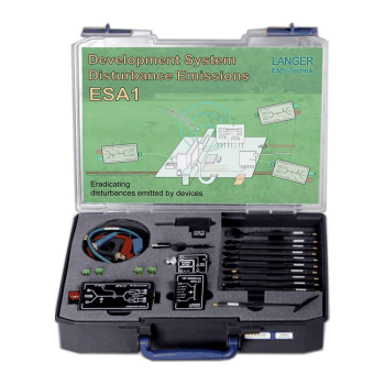
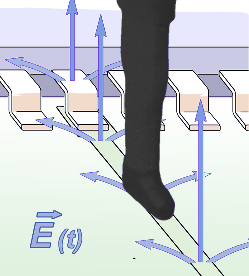
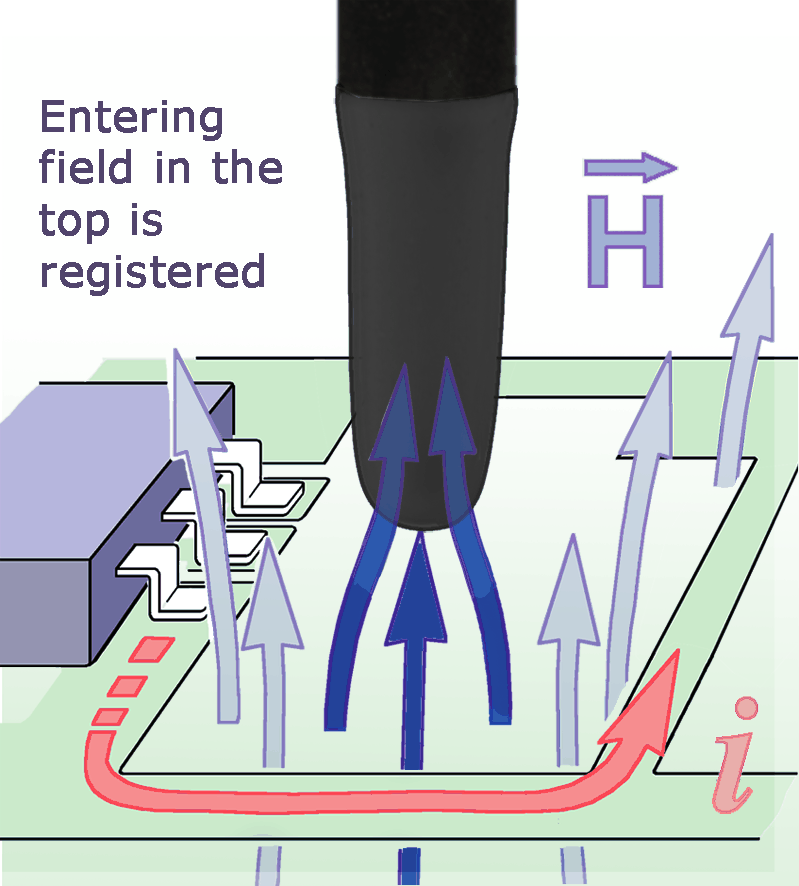
The Langer ESA1 Set brings PCB emission troubleshooting to the engineering bench. It combines H-field and E-field probes covering 30 MHz to 3 GHz, an HFW 21 RF current transformer, a 100 kHz to 3 GHz PA 203 BNC preamplifier, a 900 x 500 x 400 mm shielding tent and ChipScan-ESA software. RF-E 02 coverage is 30 MHz to 1.5 GHz. Use the tools together to locate noise sources and compare design changes.
MARKETS:
CATEGORIES:
TEST STANDARDS:
Select Options/Sizes:

ESA1 set - Datasheet
CS-ESA set - Datasheet
Z23-1 set - Datasheet
RF-B 0.3-3 - Datasheet
RF-B 3-2 - Datasheet
RF-E 02 - Datasheet
RF-E 05 - Datasheet
RF-E 10 - Datasheet
RF-R 0.3-3 - Datasheet
RF-R 3-2 - Datasheet
RF-R 50-1 - Datasheet
RF-R 400-1 - Datasheet
RF-U 2.5-2 - Datasheet
RF-U 5-2 - Datasheet
SPECIFICATIONS
ESA1 Set | EMC Emission Development System
The Langer ESA1 Set brings PCB emission troubleshooting to the engineering bench. It combines H-field and E-field probes covering 30 MHz to 3 GHz, an HFW 21 RF current transformer, a 100 kHz to 3 GHz PA 203 BNC preamplifier, a 900 x 500 x 400 mm shielding tent and ChipScan-ESA software. RF-E 02 coverage is 30 MHz to 1.5 GHz. Use the tools together to locate noise sources and compare design changes.
A coordinated bench workflow for PCB emissions
| Benefit / task | How to use the set |
|---|---|
| Find the source | Start with a larger H-field probe to find active regions, then move to smaller probes and E-field probes to separate conductor, component and electric-field effects. |
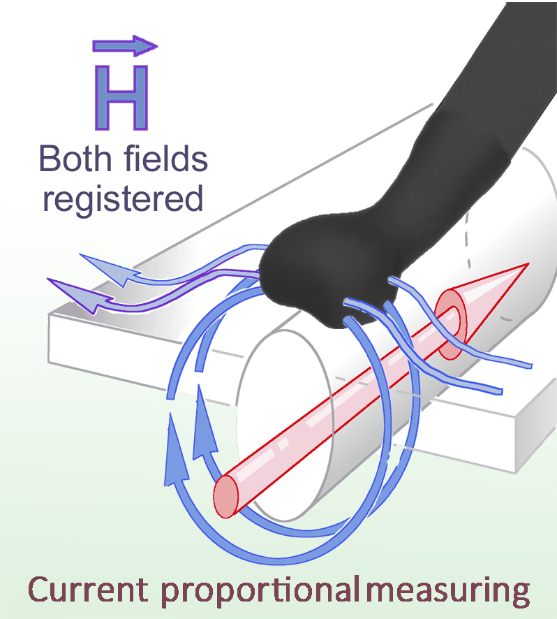
| Trace the coupling path | Use HFW 21 on DUT wiring to investigate common-mode and differential-mode RF currents and the HFA 21 bypass to evaluate the effect of capacitive suppression. |
| Compare engineering changes | Record spectra with ChipScan-ESA, hold DUT operation and geometry constant, then compare modifications such as filtering, shielding or layout changes. |
| Reduce ambient interference | Use the included Z23-1 tent when external RF masks the DUT signal. Check that cable routing and access openings preserve the measurement arrangement. |
ESA1 supports comparative development measurements. A spectrum analyzer and suitable Windows computer are required for the measurement chain and are not listed in the supplied kit. Confirm analyzer compatibility with the current ChipScan-ESA supported-device list before ordering. Final compliance assessment still requires the relevant standardized measurement.
Technical specifications
| Parameter | Specification |
|---|---|
| HFW 21 RF Current Transformer - Frequency range | 100 kHz - 1 GHz |
| HFW 21 RF Current Transformer - Current | 10 A |
| HFW 21 RF Current Transformer - Dielectric strength | 50 V |
| HFW 21 RF Current Transformer - Sizes (L x W x H) | 115 x 65 x 28 mm (current HFW 21 component listing) |
| HFA 21 RF Bypass - Capacitances | 10 pF ... 100 nF |
| HFA 21 RF Bypass - Dielectric strength | 50 V |
| Shielding tent (900x500x400) mm - Attenuated shielding | 45 dB - 50 dB / 30 MHz - 1GHz |
| Shielding tent (900x500x400) mm - Sizes (L x W x H) | (900 x 500 x 400) mm |
| Shielding tent (900x500x400) mm - Weight | 12 kg |
| Near Field Probes - Frequency range | 30 MHz - 3 GHz |
| CS-ESA software - Operating system | Windows 11/10 64-bit (latest service packs) |
| PA 203 preamplifier - Frequency range | 100 kHz - 3 GHz |
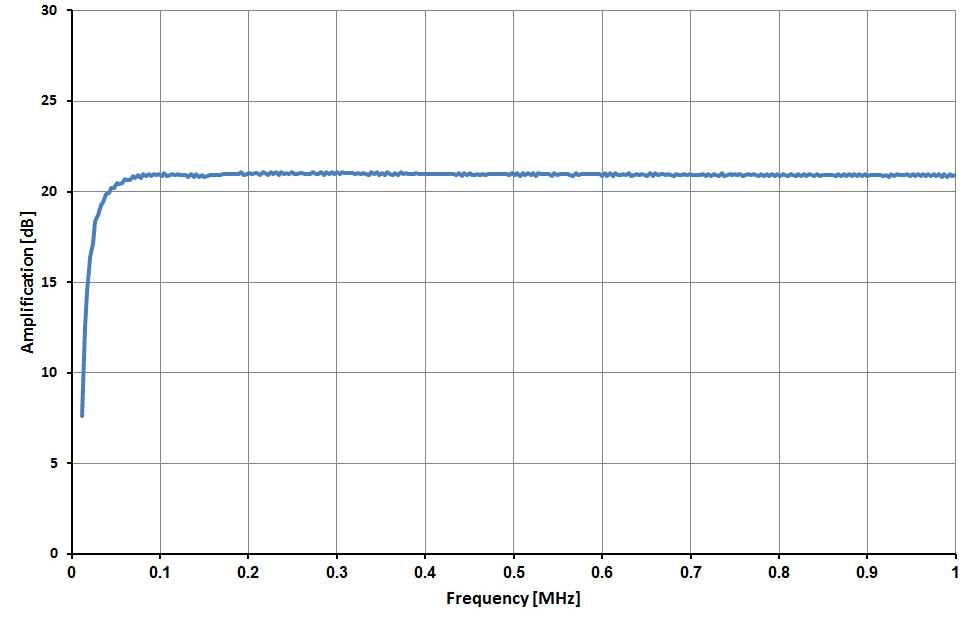
| PA 203 preamplifier - Amplification | 20 dB |
| PA 203 preamplifier - Supply voltage | 12 V DC |
| PA 203 preamplifier - Current input | 50 mA |
| PA 203 preamplifier - Max. input power | +13 dBm |
| Probe count | 11 total: 8 H-field probes and 3 E-field probes |
| RF-E 02 frequency range | 30 MHz to 1.5 GHz (individual probe limit) |
| PA 203 BNC impedance / connectors | 50 ohm / BNC |
| PA 203 BNC noise figure | 4.5 dB |
| PA 203 BNC output 1 dB compression point | 0 dBm |
| PA 203 BNC weight / dimensions | 40 g / 50 x 38 x 13 mm |
Dielectric strength is reproduced as specified by the manufacturer; it is not relabeled here as a continuous operating-voltage rating.
Included components
| Photo | Qty. | Item | Function / key specifications |
|---|---|---|---|
 |
1x | CS-ESA set | ChipScan-ESA Software / USB Operating system: Windows 11/10 64-bit (latest service packs) Monitor resolution: (1280 x 1024) px Interface: USB port for dongle HD space: 1 GB |
| 1x | Dongle | Licence Dongle USB license dongle for ChipScan-ESA acquisition. |
|
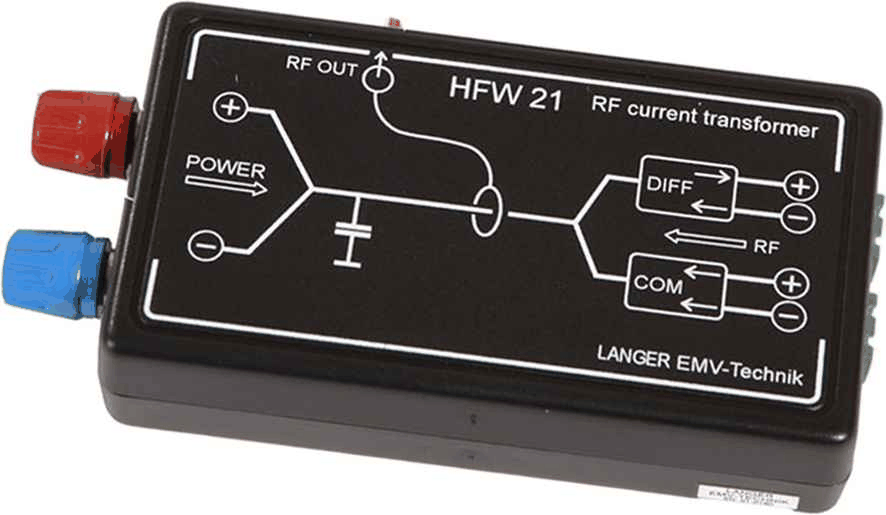 |
1x | HFW 21 | RF Current Transformer Frequency range: 100 kHz - 1 GHz Current: 10 A Dielectric strength: 50 V Sizes (L x W x H): (115 x 65 x 28) mm |
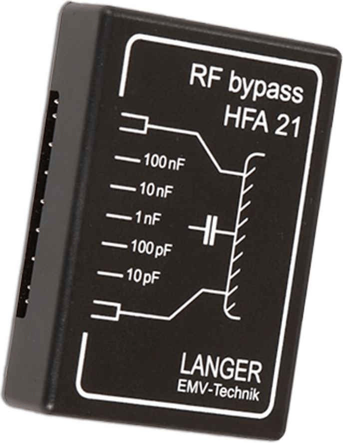 |
1x | HFA 21 | RF Bypass Capacitances: 10 pF ... 100 nF Dielectric strength: 50 V Sizes (L x W x H): (70 x 50 x 18) mm |
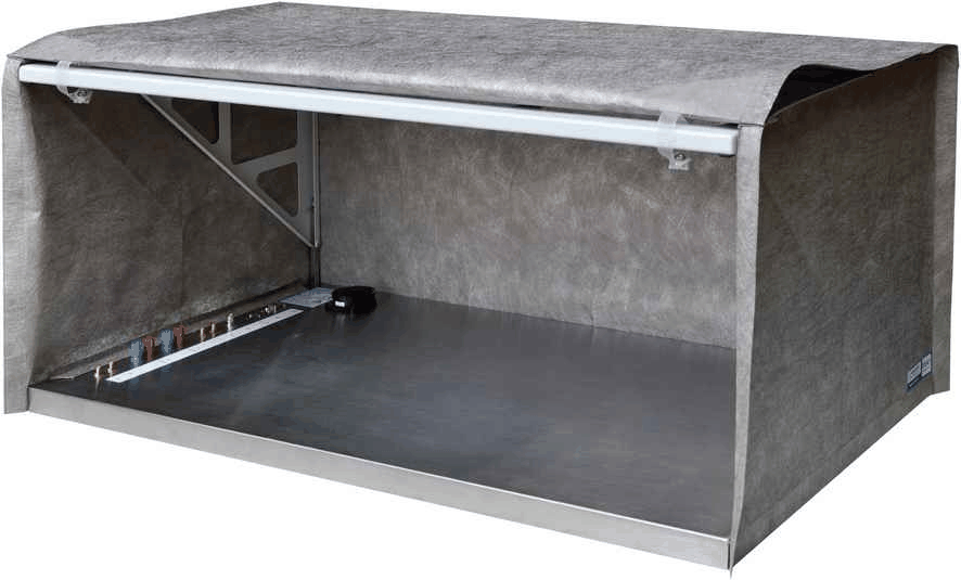 |
1x | Z23-1 set | Shielding Tent (900 x 500 x 400) mm Attenuated shielding: 45 dB - 50 dB / 30 MHz - 1 GHz Weight: 12 kg Sizes (L x W x H): (900 x 500 x 400) mm |
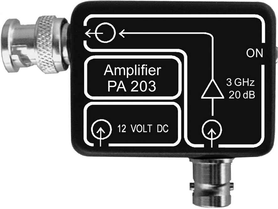 |
1x | PA 203 BNC | Preamplifier 100 kHz up to 3 GHz Frequency range: 100 kHz - 3 GHz Gain: 20 dB -1dB compression point (output): 0 dBm Noise figure: 4.5 dB |
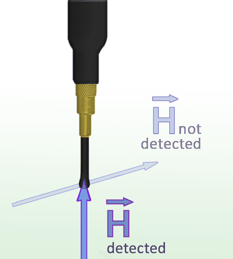 |
1x | RF-B 0.3-3 | H-Field Probe mini 30 MHz up to 3 GHz Frequency range: 30 MHz ... 3 GHz Resolution: < 1 mm Probe head dimensions: diameter approx. 2 mm |
 |
1x | RF-B 3-2 | H-Field Probe 30 MHz up to 3 GHz Frequency range: 30 MHz ... 3 GHz Resolution: approx. 2 mm Probe head dimensions: diameter approx. 4 mm |
 |
1x | RF-E 02 | E-Field Probe 30 MHz up to 1.5 GHz Frequency range: 30 MHz - 1.5 GHz Probe head dimensions: approx. (23 x 53) mm Connector - output: SMB, male, jack |
 |
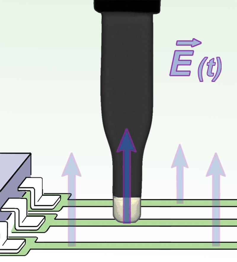
1x | RF-E 05 | E-Field Probe 30 MHz up to 3 GHz Frequency range: 30 MHz ... 3 GHz Resolution: approx. 0.6 mm Probe head dimensions: approx. (1 x 8) mm |
 |
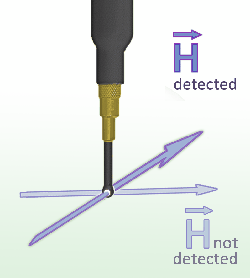
1x | RF-E 10 | E-Field Probe 30 MHz up to 3 GHz Frequency range: 30 MHz ... 3 GHz Resolution: approx. 0.2 mm Probe head dimensions: approx. (0.5 x 2) mm |
 |
1x | RF-R 0.3-3 | H-Field Probe mini 30 MHz up to 3 GHz Frequency range: 30 MHz ... 3 GHz Resolution: < 1 mm Probe head dimensions: diameter approx. 2 mm |
 |
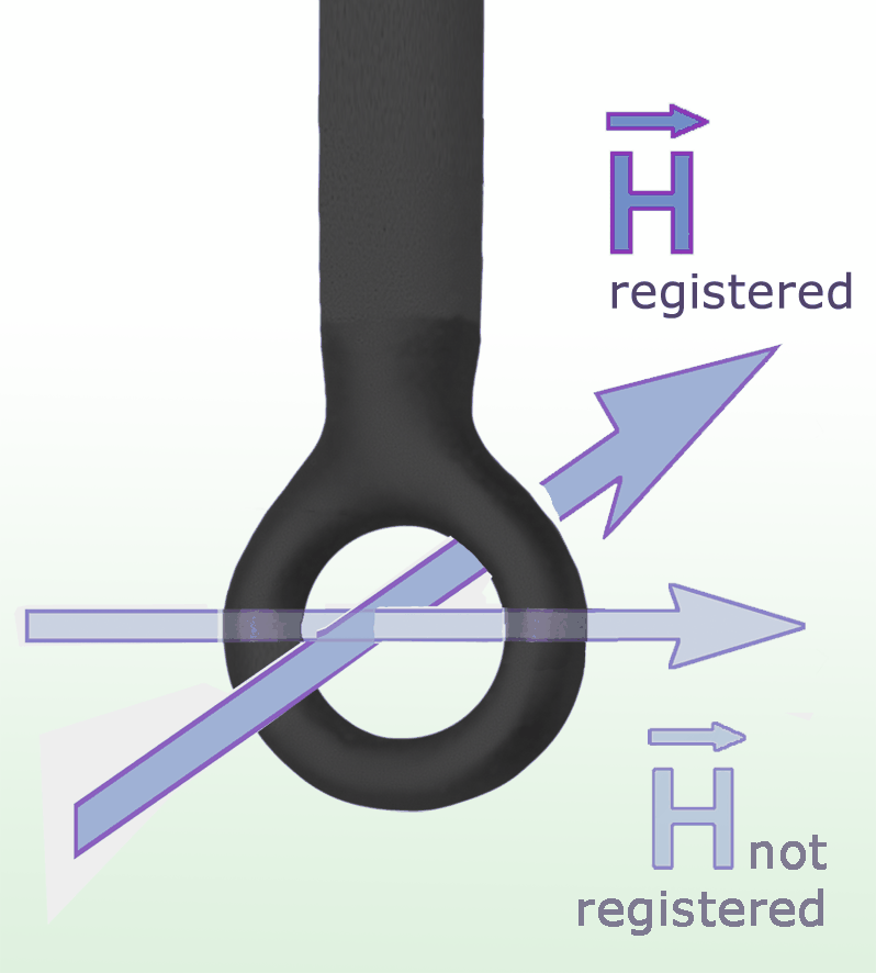
1x | RF-R 3-2 | H-Field Probe 30 MHz up to 3 GHz Frequency range: 30 MHz ... 3 GHz Resolution: approx. 1 mm Probe head dimensions: diameter approx. 3 mm |
 |
1x | RF-R 50-1 | H-Field Probe 30 MHz up to 3 GHz Frequency range: 30 MHz ... 3 GHz Probe head dimensions: diameter approx. 10 mm Connector - output: SMB, male, jack |
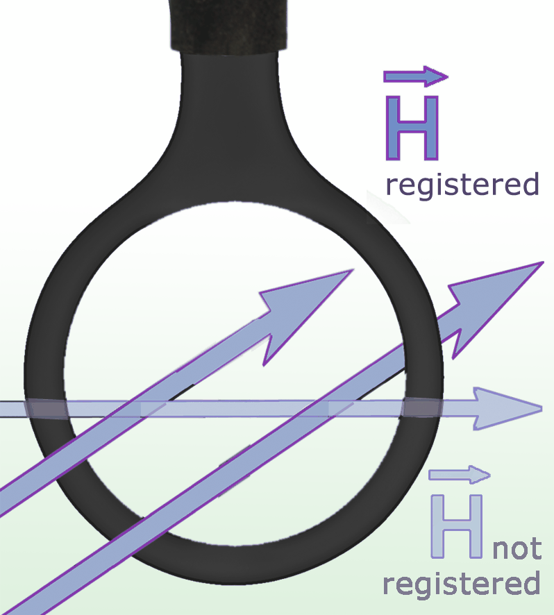 |
1x | RF-R 400-1 | H-Field Probe 30 MHz up to 3 GHz Frequency range: 30 MHz ... 3 GHz Probe head dimensions: diameter approx. 25 mm Connector - output: SMB, male, jack |
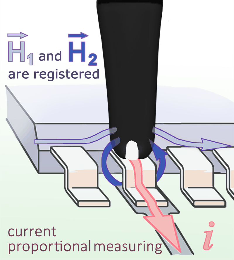 |
1x | RF-U 2.5-2 | H-Field Probe 30 MHz up to 3 GHz Frequency range: 30 MHz ... 3 GHz Resolution: approx. 0.5 mm Probe head dimensions: diameter approx. 4 mm |
 |
1x | RF-U 5-2 | H-Field Probe 30 MHz up to 3 GHz Frequency range: 30 MHz ... 3 GHz Resolution: approx. 5 mm Probe head dimensions: approx. (6 x 6) mm |
| 1x | ESA1 acc | Accessories Accessory pack for the supplied measurement tools: laboratory leads, measuring cables, connections and other setup parts. |
|
 |
1x | NT FRI EU | Power Supply Unit Plug-in power supply for the PA 203 measurement chain. Confirm the supplied mains plug for North America. |
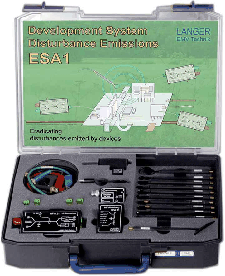
| 1x | ESA1 case | System case Protective system case for storing and transporting the kit. |
|
| 1x | ESA1 m | User Manual Operating instructions for the measurement system. |
ChipScan-ESA software and computer requirements
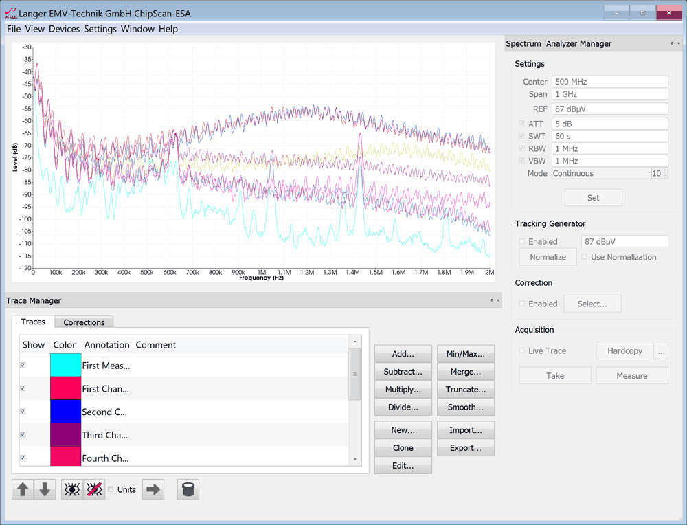
ChipScan-ESA controls a compatible spectrum analyzer, records and organizes traces, and supports calculations using stored data, correction curves and constants. The USB license dongle is included. The computer and spectrum analyzer are supplied separately.
| Requirement | Manufacturer specification |
|---|---|
| Operating system | Windows 11/10 64-bit (latest service packs) |
| Monitor resolution | (1280 x 1024) px |
| Interface | USB port for dongle |
| HD space | 1 GB |
| Graphics card | min. OpenGL 4.0 |
| Processor | Intel Core i5 2 GHz |
| Memory | 2 GB |
| Graphics card | AMD Radeon 7750 |
Measurement setup and response charts
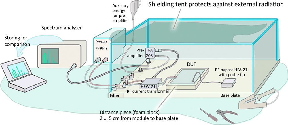
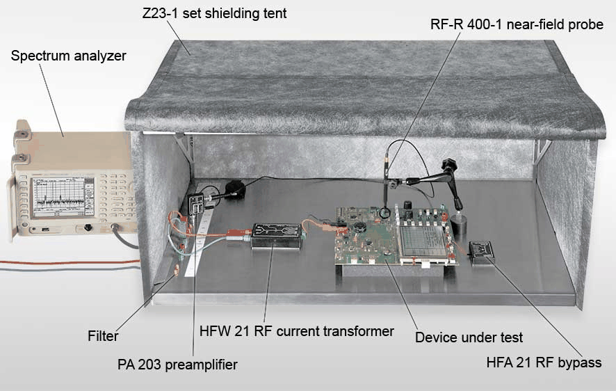
| Illustration | What it shows |
|---|---|
 |
ESA1 measurement-chain diagram |
 |
Example bench arrangement; analyzer, computer and DUT shown for illustration |
 |
PA 203 low-frequency gain detail from the ESA1 literature |
Datasheets
| Document | Open PDF |
|---|---|
| ESA1 set - datasheet | View PDF |
| CS-ESA set - datasheet | View PDF |
| Z23-1 set - datasheet | View PDF |
| RF-B 0.3-3 - datasheet | View PDF |
| RF-B 3-2 - datasheet | View PDF |
| RF-E 02 - datasheet | View PDF |
| RF-E 05 - datasheet | View PDF |
| RF-E 10 - datasheet | View PDF |
| RF-R 0.3-3 - datasheet | View PDF |
| RF-R 3-2 - datasheet | View PDF |
| RF-R 50-1 - datasheet | View PDF |
| RF-R 400-1 - datasheet | View PDF |
| RF-U 2.5-2 - datasheet | View PDF |
| RF-U 5-2 - datasheet | View PDF |
Related measurement tools
| Photo | Product | Key specifications |
|---|---|---|
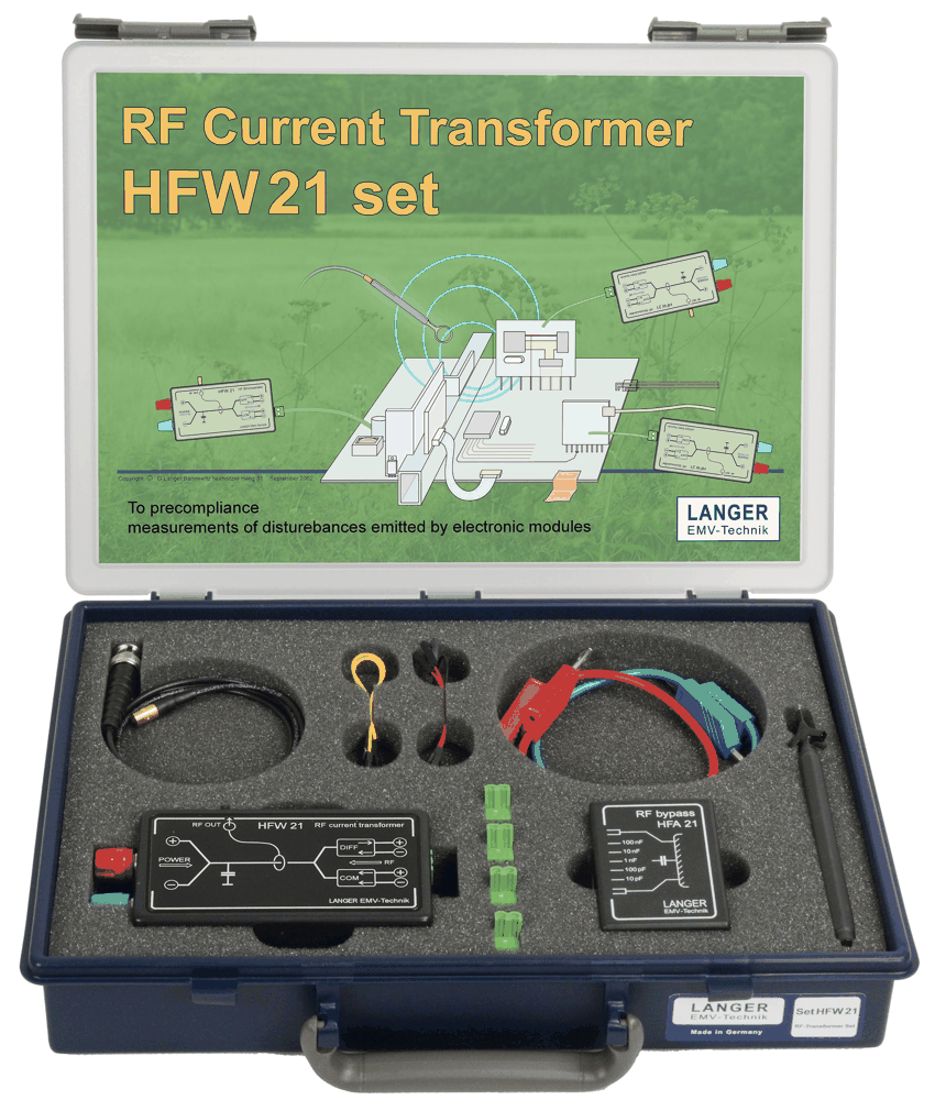 |
HFW 21 set | 100 kHz to 1 GHz | 10 A current rating | 50 V dielectric strength | Common-mode / differential-mode |
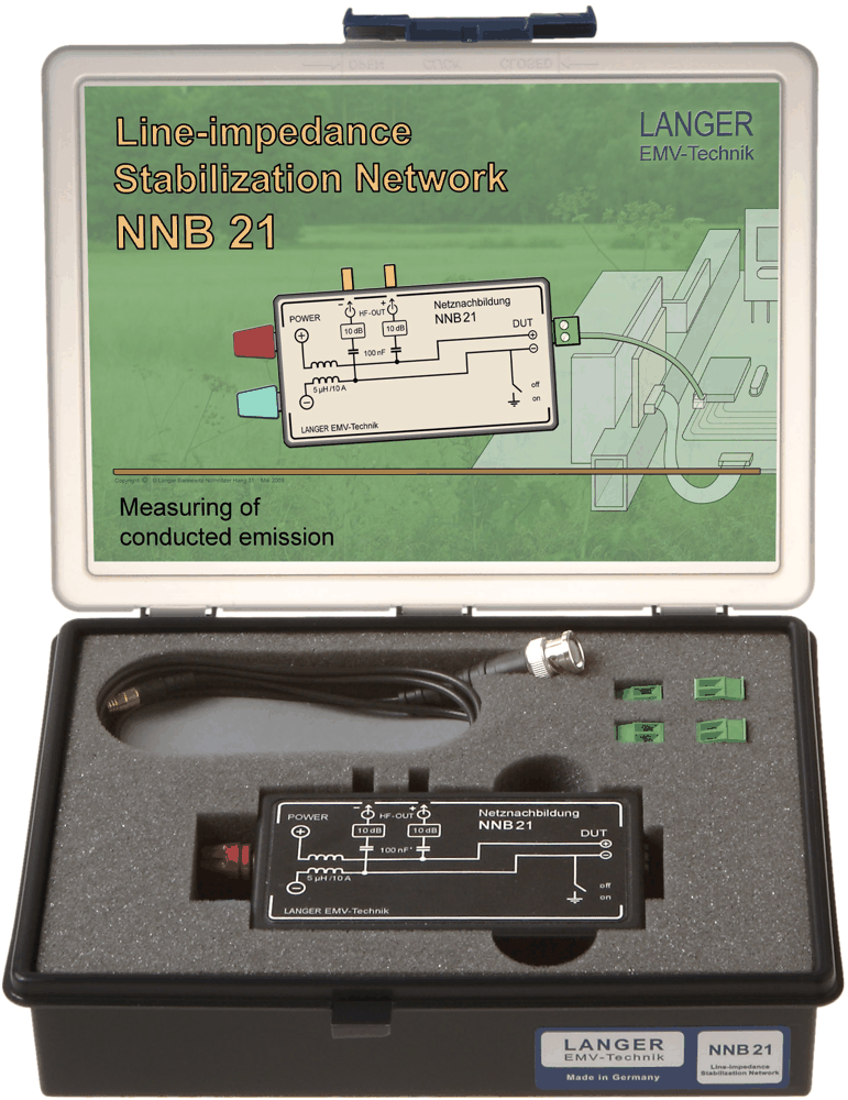 |
NNB 21 set | 100 kHz to 1 GHz | 2 measurement channels | 10 A | 10 dB internal attenuation | Less than 20 milliohm |
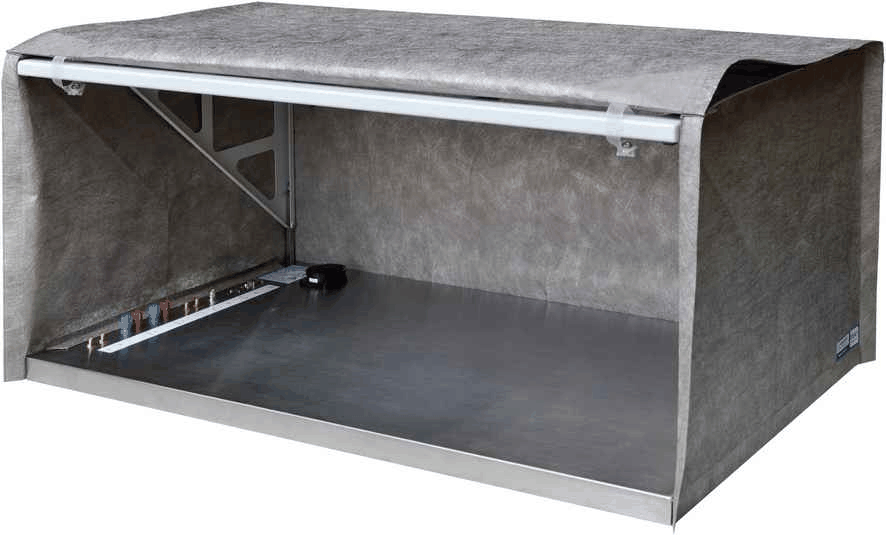 |
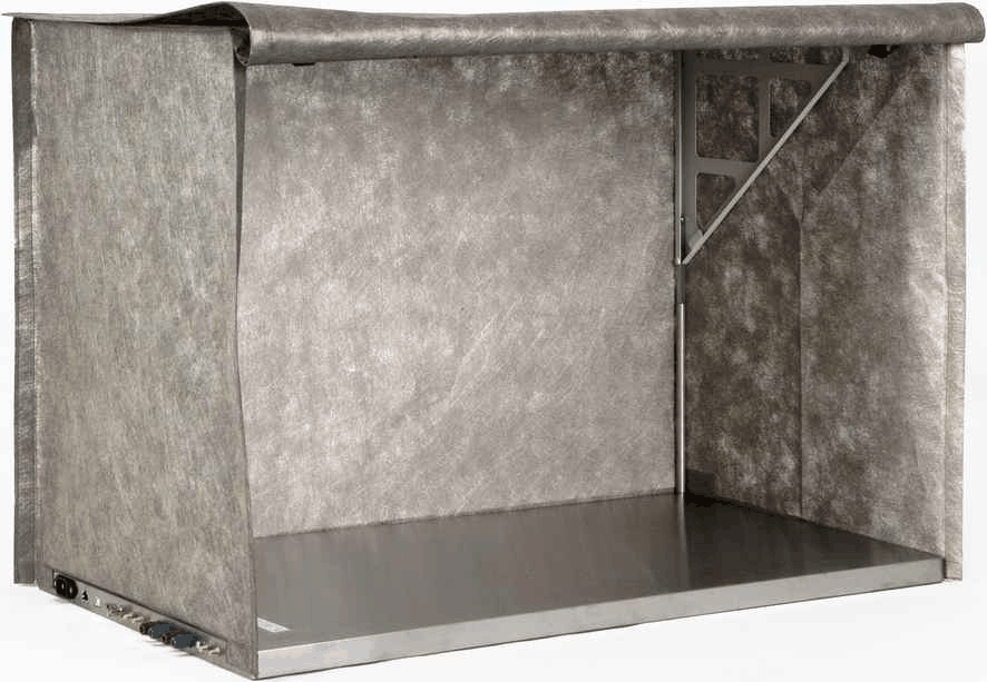
Z23-1 set | 900 x 500 x 400 mm | 45-50 dB from 30 MHz to 1 GHz | 12 kg | Ground plate + cover + frame |
Practical questions
| Question | Answer |
|---|---|
| Does the set include a spectrum analyzer? | No spectrum analyzer or computer appears in the scope of delivery. Confirm a compatible analyzer and computer before completing the system. |
| Are all eleven probes specified to 3 GHz? | Ten probes cover 30 MHz to 3 GHz. RF-E 02 covers 30 MHz to 1.5 GHz; use each probe within its individual range. |
| Does ESA1 replace a compliance test? | Use it to locate sources and compare design changes during development. Compliance results depend on the complete standardized test setup. |
Product videos
Selection guide - compare development-stage measurement sets
These sets perform different jobs. ESA1 combines several tools, while the other sets target a particular measurement task. Click a set to review its complete contents.
| Kit | Set | Type | Key range / size | Included tools | Choose it for |
|---|---|---|---|---|---|
 |
ESA1 set | Integrated PCB emissions toolkit | 11 probes: 30 MHz to 3 GHz; RF-E 02 to 1.5 GHz; HFW 21: 100 kHz to 1 GHz | Tent, transformer, bypass, preamplifier, probes and software | Coordinated source finding and design comparisons |
|
HFW 21 set | RF current transformer | 100 kHz to 1 GHz; 10 A | HFW 21, HFA 21, cable, accessories and case | Separate common-mode and differential-mode RF currents |
|
Z23-1 set | EMC shielding tent | 900 x 500 x 400 mm; 12 kg | Ground plate, cover and folding frame | 45-50 dB attenuation at 30 MHz to 1 GHz |
 |
Z23-2 set | Taller EMC shielding tent | 900 x 500 x 650 mm; 13 kg | Ground plate, taller cover, frame and adapters | 250 mm more height than Z23-1 |
|
NNB 21 set | Two-channel LISN | 100 kHz to 1 GHz; 10 A; 10 dB internal attenuation | NNB 21, one cable, accessories and case | Conducted disturbance measurements on DUT wiring |
OTHER PRODUCTS IN THE SAME CATEGORY:
EMSCOPE-RX4, 9kHz - 110MHz, 4 channel Receiver for 3 phase
EMSCOPE-RX2, 9kHz - 110MHz, 2 channel Receiver
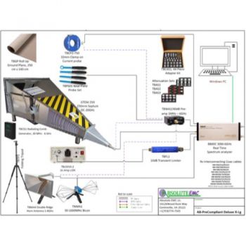
AB-Precompliant Test Kits
Harmonics & Flicker Test System 30kVA (43A) & 50kVA (75A) 1 & 3-Phase
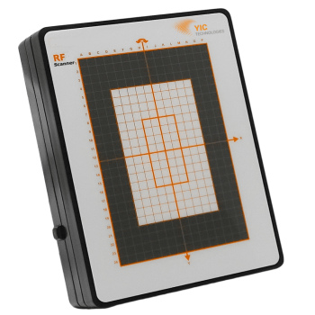
RFScanner, Antenna Pattern measurement, 300MHz - 6 GHz
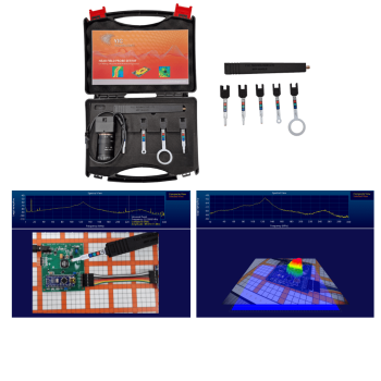
NFPKIT, EM Near Field Probe Kit w/Camera & Software
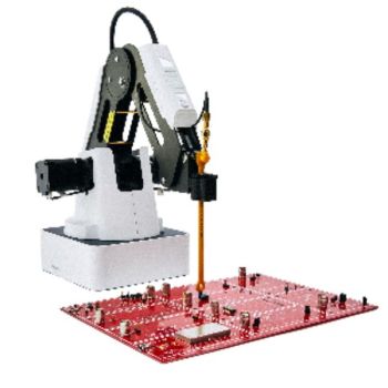
EMProbe: 9kHz- 18 GHz, 0.2mm resolution, EMC robotic scanner
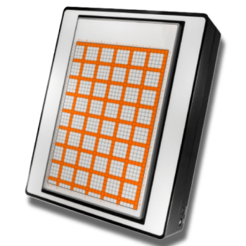
EMScannerR: 150 kHz- 8 GHz, 0.06mm resolution, EMC desktop scanner
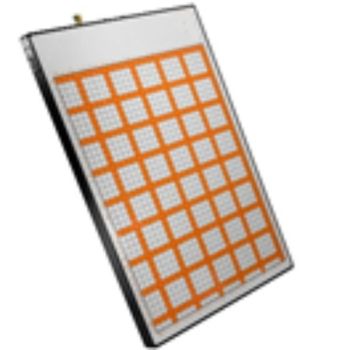
EMScanner: 150 kHz- 8 GHz, 3.5mm Resolution, EMC desktop scanner
EMScannerR+: 150 kHz- 6 GHz, w/ Real-Time Spectrum Analyzer, EMC desktop scanner
EMScanner+: 150 kHz- 6 GHz, w/ Real-Time Spectrum Analyzer, EMC desktop scanner
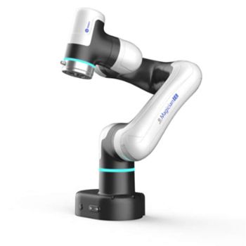
EMProbe-DBM-E6 — 6-Axis Robotic Near-Field EMI Diagnostics on the Bench
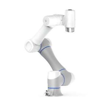
EMProbe CR5 - Custom Large-Reach Robotic EMI Scanning System
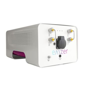
EMSCOPE Click Meter for CISPR 14-1
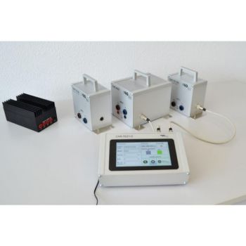
CAR TE 21 Transient Emission Test to ISO 7637-2
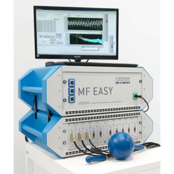
MF EASY, DC-400 kHz, MAGNETIC FIELD EXPOSURE ASSESSMENT SYSTEM
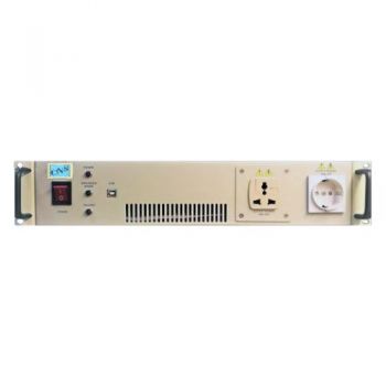
HFa-1-16-Ref, 16 Amp single phase Harmonics and Flicker w/ Impedance Reference

HFa-1S, 16 Amp single phase Harmonics and Flicker
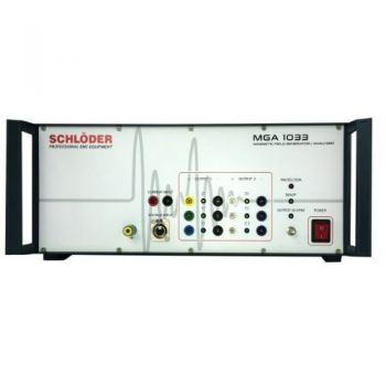
MGA 1033; Magnetic Immunity DC-250 kHz, 800 Watts