EMProbe CR5 - Custom Large-Reach Robotic EMI Scanning System
Custom configuration | 6-axis robot | 900 mm working-radius example
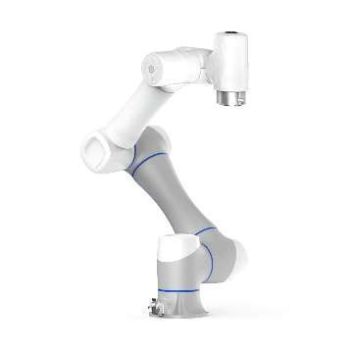
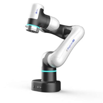
EMProbe CR5 is a custom near-field scanning solution for larger DUTs and applications that need more reach than a compact bench arm. It combines a six-axis collaborative robot, application-specific probe mounting and EMViewer scan control with a compatible external spectrum analyzer. Each system is configured around the DUT geometry, probe selection, workspace and measurement objectives. Request a quotation for your application.
PARTNER:
MARKETS:
CATEGORIES:
TEST STANDARDS:
Select Options/Sizes:

CR5 Custom Solution Overview - Example Configuration
SPECIFICATIONS
EMProbe CR5 - Custom Large-Reach Robotic EMI Scanning System
Custom configuration | 6-axis robot | 900 mm working-radius example

Application and capabilities
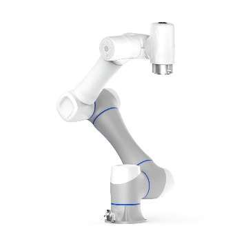
EMProbe CR5 is a custom near-field scanning solution for larger DUTs and applications that need more reach than a compact bench arm. It combines a six-axis collaborative robot, application-specific probe mounting and EMViewer scan control with a compatible external spectrum analyzer. Each system is configured around the DUT geometry, probe selection, workspace and measurement objectives. Request a quotation for your application.
- Define scan paths around the actual DUT geometry and component access.
- Integrate Y.I.C. probes or an agreed third-party probe with a custom mounting adapter.
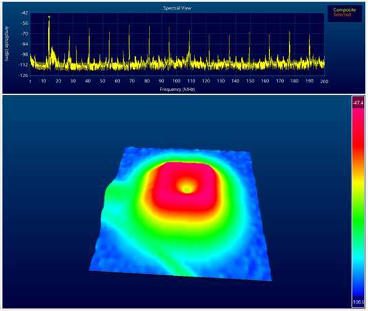
- Automate motion and measurement synchronization with 2D/3D field maps, heat maps, logging and report/data export.
- Scope robot mounting, fixtures, cable management and on-site integration for the intended application.
Technical specifications
| Specification | Details |
|---|---|
| Configuration status | Custom solution; the following values describe the supplied CR5 proposal example, not a fixed catalog package |
| Robot axes | 6 |
| Payload | 5 kg |
| Working radius | 900 mm; approximately 1,800 mm side-to-side envelope before fixture/probe constraints |
| Position repeatability | +/-0.02 mm |
| Maximum TCP speed | 3 m/s robot capability; not a guaranteed measurement scan speed |
| Maximum joint speed | 180 degrees/s |
| Robot mass | 23 kg |
| Robot supply | 48 V DC |
| Communication | Ethernet TCP/IP |
| Software | EMViewer 2.0: scan control, acquisition and field mapping |
| PC | Windows 11 PC/laptop |
| Probe mounting | Custom adapter; the proposal example accommodates customer-specified Langer probes |
| Probe set | Five Y.I.C. electric/magnetic probes in the proposed configuration; final ranges and inclusions defined in quotation |
| RF frequency range | Set by chosen probes, cable and compatible spectrum analyzer |
| Collaborative functions | Integrated robot safety functions; installation and risk assessment depend on the application |
CR5 table sizes and workspace planning
Use these table-size recommendations as a starting point when planning your CR5 installation. Confirm the final table, robot mounting and usable workspace for the selected DUT and fixtures.
| Table size | Recommendation | Use |
|---|---|---|
| 800 x 800 mm | Small | Robot only / limited workspace |
| 1,000 x 1,000 mm | Minimum practical | Compact applications |
| 1,200 x 1,200 mm | Recommended | Good general-purpose setup |
| 1,500 x 1,000 mm | Excellent | Robot plus workpieces and fixtures |
| 1,500 x 1,500 mm | Very spacious | Training, demonstrations, multiple stations |
System components
Proposed project scope
- Robot and probe-set selection defined in the project quotation
- Custom probe mounting assembly and mechanical integration
- Robot motion programming/interface and EMViewer integration
- Functional test scope and user documentation agreed in the quotation
User-supplied or separately specified
- Compatible external spectrum analyzer unless expressly quoted
- Windows 11 PC/laptop
- DUT dimensions, mass, required scan surfaces and operating conditions
- Probe models/drawings and required frequency range
- Suitable robot mounting, work area and commissioning arrangements
Measurement workflow
| Step | What the engineer does |
|---|---|
| 1. Configure | Choose the frequency band, analyzer settings and scan area; connect the DUT and measurement system. |
| 2. Locate | Run a spectral or spatial scan to identify frequencies and emission hot spots. |
| 3. Investigate | Refine the region, probe position or resolution while keeping the setup controlled. |
| 4. Compare | Repeat after a design change, compare results and retain maps and reports. |
Software and configuration
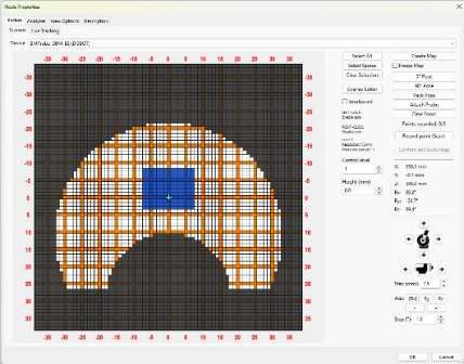
EMViewer links scan position with RF measurements. Available modes include spectral sweeps, spatial hot-spot maps and combined scans. Confirm the supported software release, analyzer driver, license and support term when configuring the system.
EMViewer software information | Spectrum-analyzer compatibility
Working radius is not a guaranteed rectangular scan area. The proposal separately mentions 1,096 mm maximum reach; the usable measurement envelope must be confirmed with the probe, fixture and robot configuration.
There is no fixed CR5 datasheet or standard package. Installation, training, on-site commissioning, analyzer supply and final acceptance testing are agreed in the quotation.
There is no fixed CR5 datasheet or standard package. Installation, training, on-site commissioning, analyzer supply and final acceptance testing are agreed in the quotation.
Custom solution overview
Compare Y.I.C. near-field scanning solutions
Choose the measurement method, analyzer configuration and workspace that fit your DUT. Select a product name or picture for its full details.
| Product | Method / best fit | RF coverage / analyzer | Scan area or workspace | Sampling / positioning |
|---|---|---|---|---|
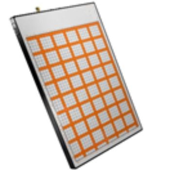 EMScanner |
Fixed H-field array Fast PCB overview and design comparisons |
150 kHz to 8 GHz External, compatible |
316 x 218 mm | 7.5 mm pitch; 3.75 mm effective |
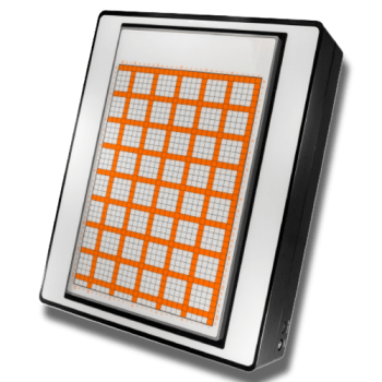 EMScannerR |
High-resolution array Dense PCB hot-spot detail |
150 kHz to 8 GHz External, compatible |
316 x 218 mm | 7.5 to 0.06 mm; 8 levels |
 EMScanner+ |
Fixed H-field array Fast PCB overview and design comparisons |
150 kHz to 6 GHz Internal BB60C |
316 x 218 mm | 7.5 mm pitch; 3.75 mm effective |
 EMScannerR+ |
High-resolution array Dense PCB hot-spot detail |
150 kHz to 6 GHz Internal BB60C |
316 x 218 mm | 7.5 to 0.06 mm; 8 levels |
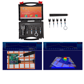 NFP Kit |
Handheld, camera-tracked Interactive troubleshooting and flexible probing |
Probe/analyzer dependent; see probe table External, compatible |
Camera field of view / setup | Manual positioning; tracking/setup dependent |
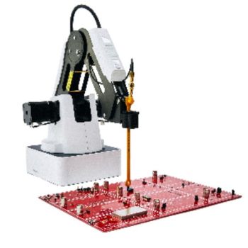 EMProbe |
Compact robotic arm Component-side and variable-height scans |
Probe/analyzer dependent; see probe table External, compatible |
300 mm radius, standard arm | 7.5 to 0.2 mm scan spacing |
 EMProbe DBM E6 |
6-axis robot Repeatable multi-angle scans |
Probe/analyzer dependent; see probe table External, compatible |
450 mm radius | 0.1 mm scan spacing; 0.01 mm repeatability |
EMProbe CR5 |
Custom 6-axis robot Larger DUTs and custom fixtures |
Selected probes and analyzer External, compatible |
900 mm working-radius example; usable scan envelope customized | +/-0.02 mm robot repeatability; scan spacing specified per project |
Array spacing, effective resolution, robotic scan spacing and robot repeatability describe different properties. Probe systems do not have one continuous guaranteed frequency range independent of the selected probe and analyzer. CR5 values are a project example; final specifications are defined by quotation. Near-field diagnostics support EMC development and do not replace a formal emissions compliance test.
OTHER PRODUCTS IN THE SAME CATEGORY:
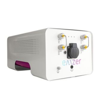
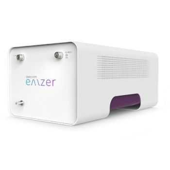
EMSCOPE-RX2, 9kHz - 110MHz, 2 channel Receiver
EMSCOPE-RX4, 9kHz - 110MHz, 4 channel Receiver for 3 phase

EMScannerR: 150 kHz- 8 GHz, 0.06mm resolution, EMC desktop scanner

EMProbe-DBM-E6 — 6-Axis Robotic Near-Field EMI Diagnostics on the Bench
EMScanner+: 150 kHz- 6 GHz, w/ Real-Time Spectrum Analyzer, EMC desktop scanner
EMScannerR+: 150 kHz- 6 GHz, w/ Real-Time Spectrum Analyzer, EMC desktop scanner
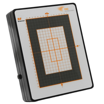
RFScanner, Antenna Pattern measurement, 300MHz - 6 GHz

NFPKIT, EM Near Field Probe Kit w/Camera & Software

EMProbe: 9kHz- 18 GHz, 0.2mm resolution, EMC robotic scanner
eNFPKIT, Educational Kit EM Near Field Probe Kit w/Camera & Software

EMScanner: 150 kHz- 8 GHz, 3.5mm Resolution, EMC desktop scanner
EMProbe CR5 - Custom Large-Reach Robotic EMI Scanning System
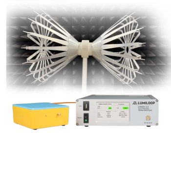
LSAOL 1.2 Laser-Powered Analog Optical Link
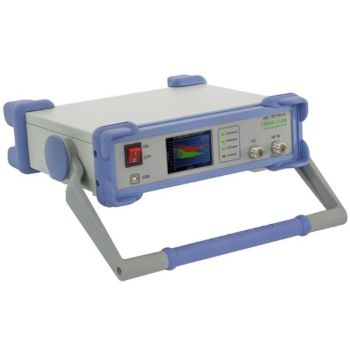
TBMR-110M DC - 110 MHz high speed EMI-Analyzer
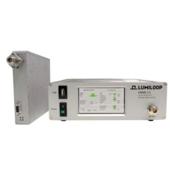
LSAOL 1.1, Laser Powered RF Link, 9kHz - 6GHz Discontinued
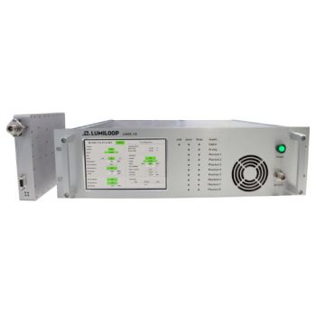
LSAOL 1.0, Laser Powered RF Link, Discontinued
EMSCOPE, 9kHz - 110MHz, 2 channel Receiver/LISN
EMSCOPE-RX4, 9kHz - 110MHz, 4 channel Receiver for 3 phase
EMSCOPE-RX2, 9kHz - 110MHz, 2 channel Receiver