Langer XFS Scanner Probes | 30 MHz to 6 GHz
30 MHz to 6 GHz | 4 probe models | Passive | SMA connection
XFS passive scanner probes extend PCB near-field investigations to 6 GHz. Choose an R or B magnetic geometry or a fine E-field electrode to suit the coupling path and access to the structure being measured.
MARKETS:
CATEGORIES:
TEST STANDARDS:
Select Options/Sizes:

XFS-R 3-1 - Datasheet
XFS-B 3-1 - Datasheet
XFS-E 10 - Datasheet
XFS-E 09s - Datasheet
SPECIFICATIONS
XFS scanner probes
XFS passive scanner probes extend PCB near-field investigations to 6 GHz. Choose an R or B magnetic geometry or a fine E-field electrode to suit the coupling path and access to the structure being measured.
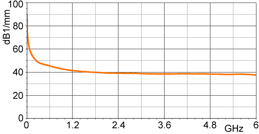
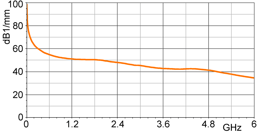
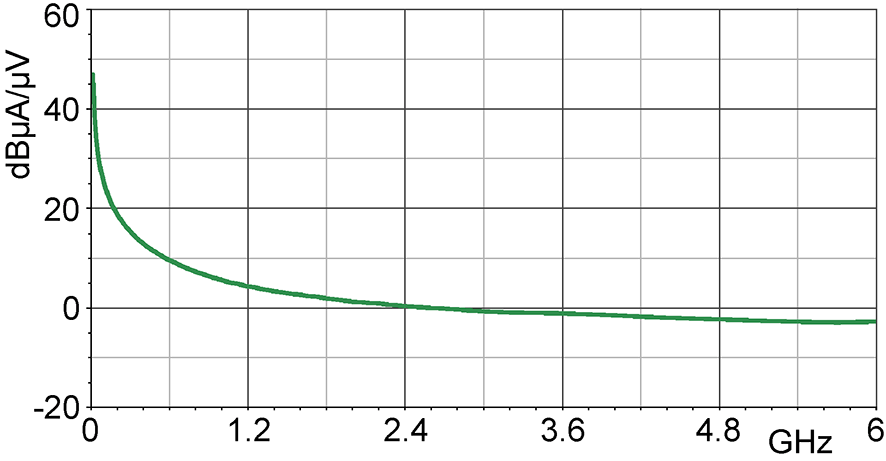
All published scalar specifications are consolidated below. Click each small response, correction-curve or geometry image to open the full-size image in a new tab. Missing numeric resolution or length values are not inferred from model names or photographs.
| Specification / view | XFS-R 3-1 | XFS-B 3-1 | XFS-E 10 | XFS-E 09s |
|---|---|---|---|---|
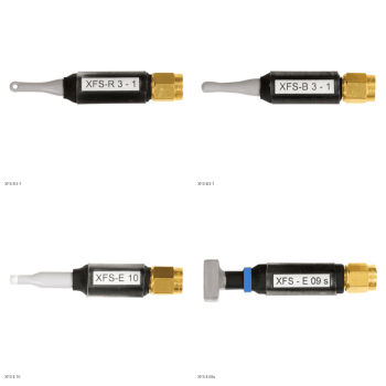
| Product picture | 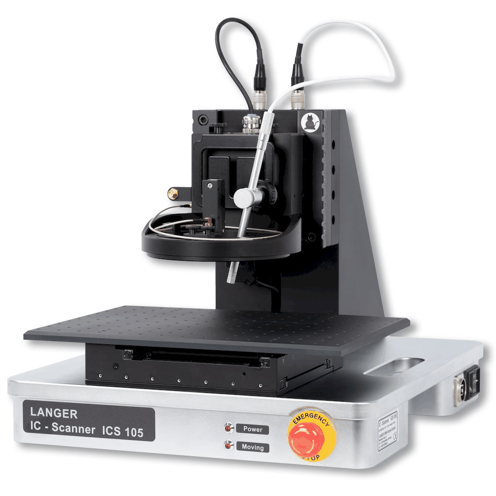 |
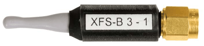
 |
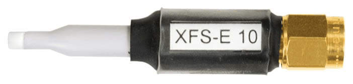
 |
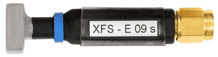
 |
| Field type | H-field | H-field | E-field | E-field |
| Frequency range | 30 MHz ... 6 GHz | 30 MHz ... 6 GHz | 30 MHz ... 6 GHz | 30 MHz ... 6 GHz |
| Resolution | approx. 1 mm | approx. 2 mm | approx. 0.2 mm | approx. 0.2 mm |
| Probe head dimensions | diameter approx. 3 mm | diameter approx. 4 mm | approx. (0.5 x 2) mm | approx. (10 x 10) mm |
| Connector - output | SMA, male, jack | SMA, male, jack | SMA, male, jack | SMA, male, jack |
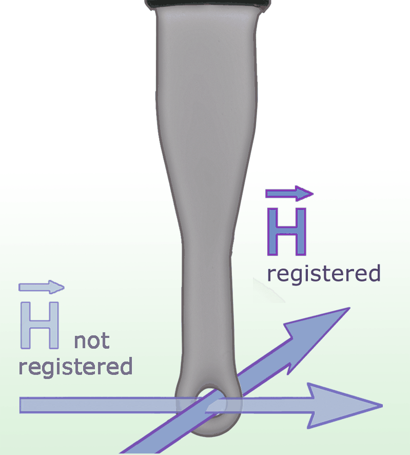
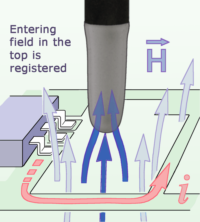
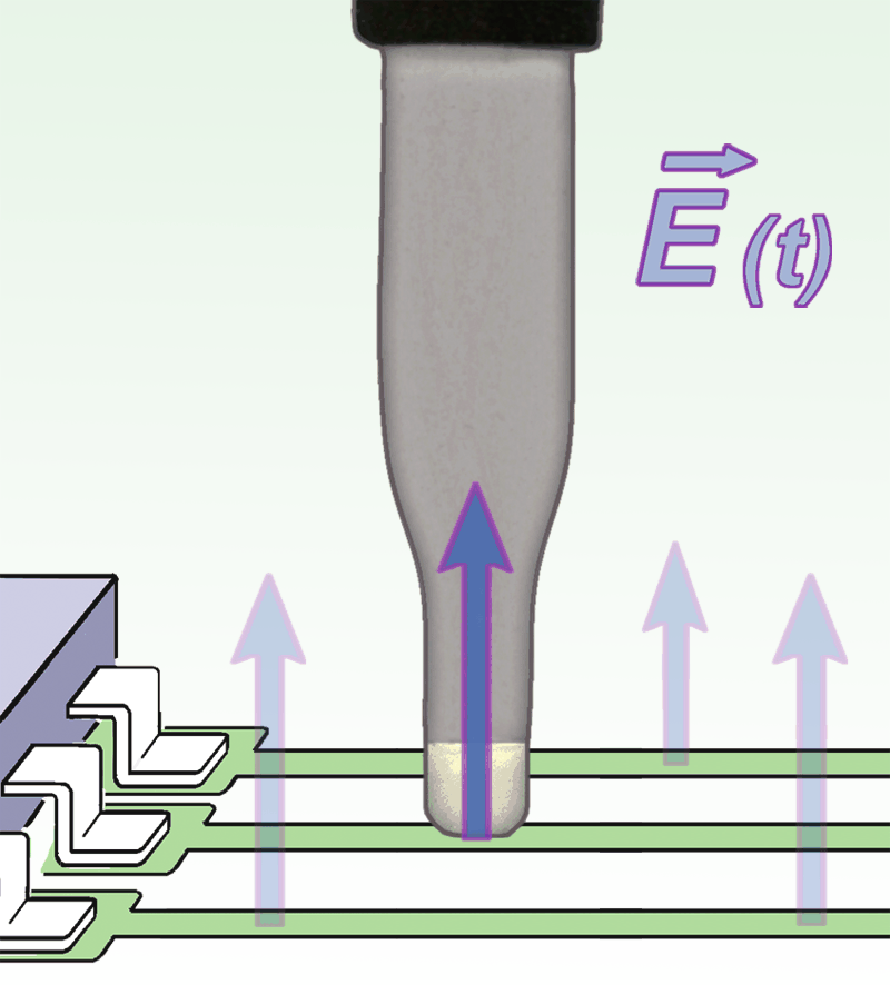
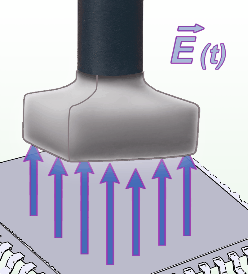
| Use and orientation | H-field; direct high-resolution mapping at traces, IC packages, decoupling capacitors and EMC components, extending coverage to 6 GHz. | H-field; coil orthogonal to the shaft. With the shaft vertical, the sensing coil can be placed directly at the board, including between tall components. | E-field; approximately 0.2 mm electrode width, for 0.1 mm traces and individual IC pins. Position at the structure being measured. | E-field; detects fields above the IC surface. Manufacturer describes measurements from 0.5 to 10 mm above an assembly; choose the spacing for the task. |
| Sensing orientation Click image for full view |
 Sensing orientation / measuring principle |
 Sensing orientation / measuring principle |
 Sensing orientation / measuring principle |
 Sensing orientation / measuring principle |
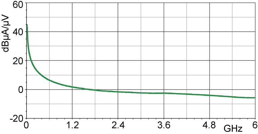
| Frequency response Click image for full view |
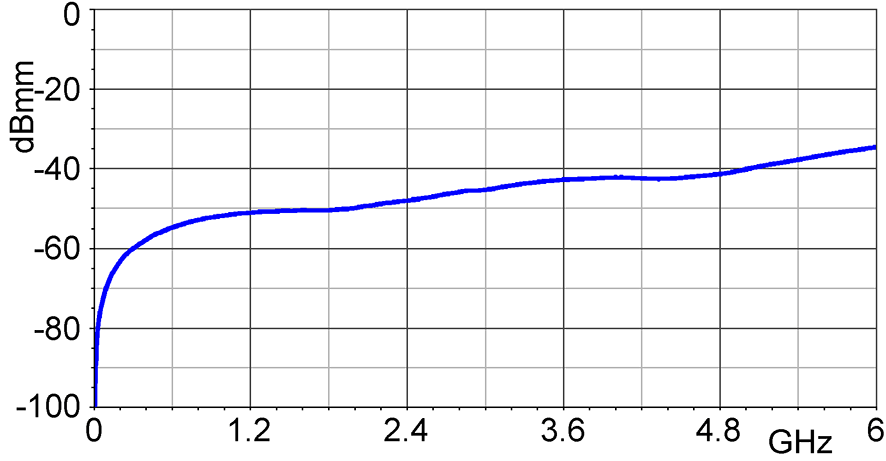 Frequency response [dBuV] / [dBuA/m] |
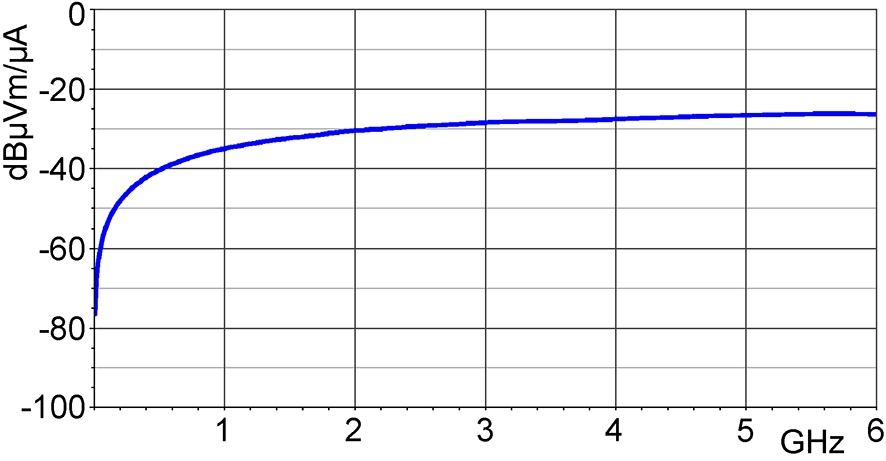 Frequency response [dBuV] / [dBuA/m] |
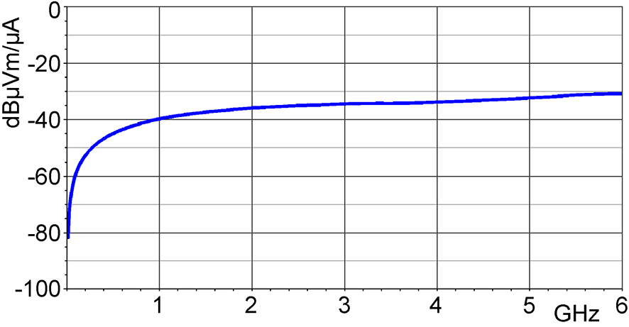 Frequency response [dBuV] / [dBuA/m] |
 Frequency response [dBuV] / [dBuA/m] |
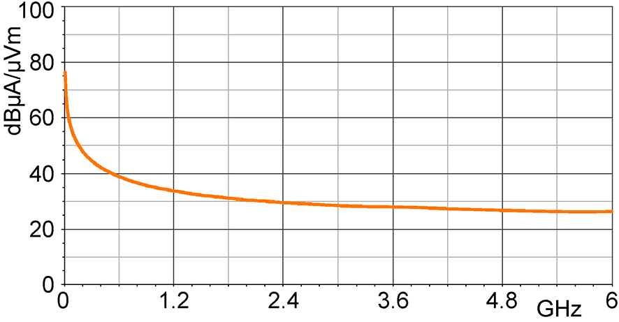
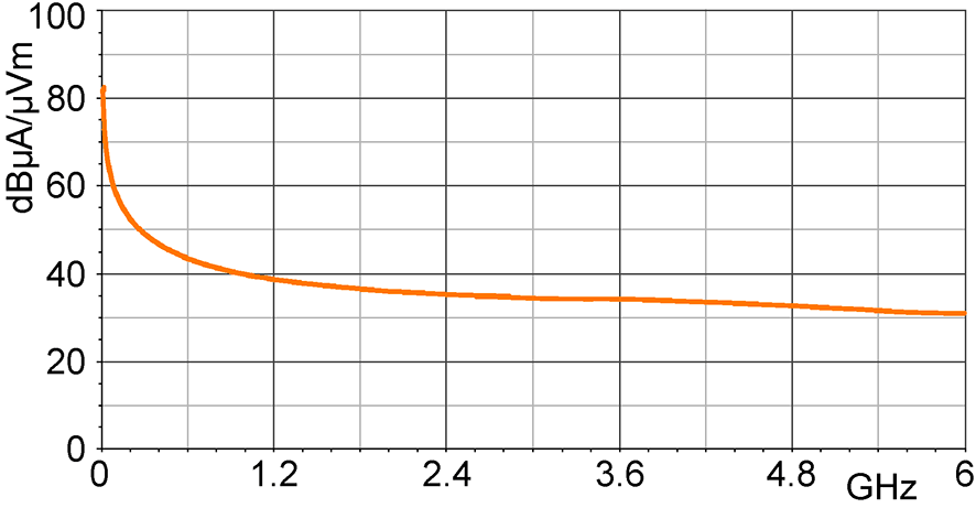
| H-field correction curve Click image for full view |
 H-field correction curve [dBuA/m] / [dBuV] |
 H-field correction curve [dBuA/m] / [dBuV] |
Not published | Not published |
| Current correction curve Click image for full view |
 Current correction curve [dBuA] / [dBuV] |
 Current correction curve [dBuA] / [dBuV] |
Not published | Not published |
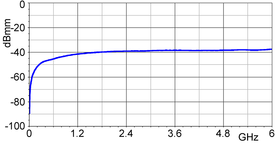
| E-field correction curve Click image for full view |
Not published | Not published |  E- field correction curve [dBuV/mm] / [dBuV] |
 E- field correction curve [dBuV/mm] / [dBuV] |
Using the curves and geometries
Frequency-response plots show the model-specific response. H-field, E-field and current correction curves are separate quantities: use the appropriate curve, units, distance and setup when converting receiver voltage to a field or current estimate. A probe is directional; keep the sensing orientation and probe-to-DUT spacing consistent between scans. The source tables use both "SMA male plug" and "SMA male jack" wording; verify the mating cable rather than silently treating the terms as different probe genders.
Datasheets and reference documents
| Product | Document |
|---|---|
| XFS-R 3-1 | XFS-R 3-1 - Datasheet |
| XFS-B 3-1 | XFS-B 3-1 - Datasheet |
| XFS-E 10 | XFS-E 10 - Datasheet |
| XFS-E 09s | XFS-E 09s - Datasheet |
Scanner probe family comparison
| Family | Models | Coverage | Field types | Choose for |
|---|---|---|---|---|
 LFS |
1 | 100 kHz-50 MHz | H | Low-frequency switching-current and magnetic-field mapping. |
 RFS |
7 | 30 MHz-3 GHz | H and E | General PCB investigations with large-area and fine-resolution geometries. |
| XFS |
4 | 30 MHz-6 GHz | H and E | PCB near-field mapping when coverage above 3 GHz is needed. |
The passive scanner probes below have model-specific SMA connections and no power supply in their published specification. ICR near-field microprobes are a separate precision-probe class; use the existing ICR near-field microprobe range when micrometer-scale sensing is needed.
OTHER PRODUCTS IN THE SAME CATEGORY:
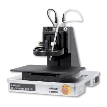
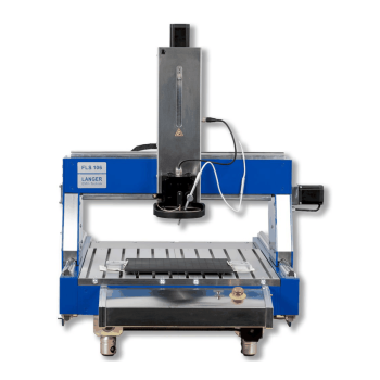
Langer FLS 106 IC | Large-area scanner with probe rotation
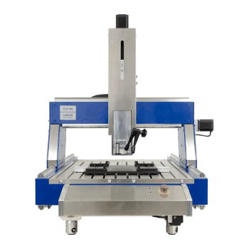
Langer FLS 106 PCB | Large-area three-axis PCB scanner
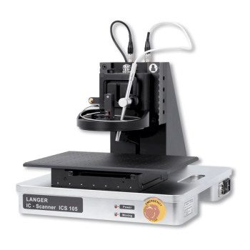
Langer Scanner and Scanner Probe Comparison Guide
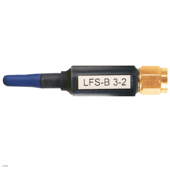
Langer LFS Scanner Probes | 100 kHz to 50 MHz
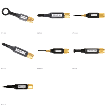
Langer RFS Scanner Probes | 30 MHz to 3 GHz
Langer XFS Scanner Probes | 30 MHz to 6 GHz
EMProbe CR5 - Custom Large-Reach Robotic EMI Scanning System
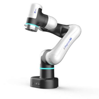
EMProbe-DBM-E6 — 6-Axis Robotic Near-Field EMI Diagnostics on the Bench
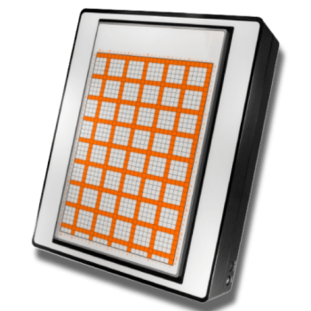
EMScanner+: 150 kHz- 6 GHz, w/ Real-Time Spectrum Analyzer, EMC desktop scanner
EMScannerR+: 150 kHz- 6 GHz, w/ Real-Time Spectrum Analyzer, EMC desktop scanner
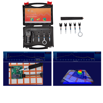
NFPKIT, EM Near Field Probe Kit w/Camera & Software
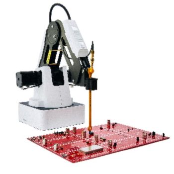
EMProbe: 9kHz- 18 GHz, 0.2mm resolution, EMC robotic scanner
EMScanner: 150 kHz- 8 GHz, 3.5mm Resolution, EMC desktop scanner
EMScannerR: 150 kHz- 8 GHz, 0.06mm resolution, EMC desktop scanner
Langer E1 set | PCB Immunity Development System
Langer Scanner and Scanner Probe Comparison Guide
Langer Handheld Near-Field Probes Selection Guide
Langer ICR Near-Field Microprobe Selection Guide
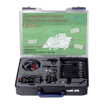
Langer ESA1 Set | EMC Emission Development System