
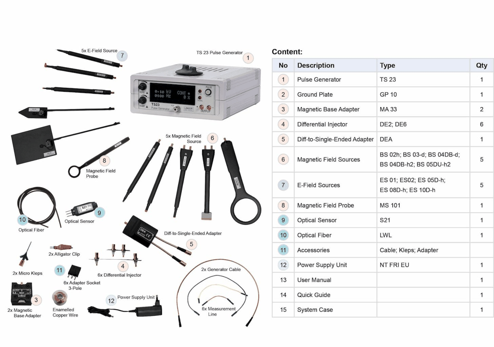
Langer E2 set | TS 23 PCB Immunity Development System
Up to 2.2 kV adjustable | 1.5 ns rise | Adjustable 1.5 kHz repetition | Both polarities | 50 Mbps optical sensor
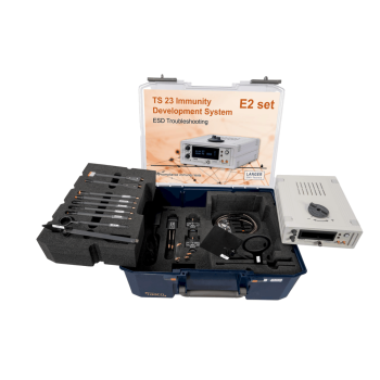
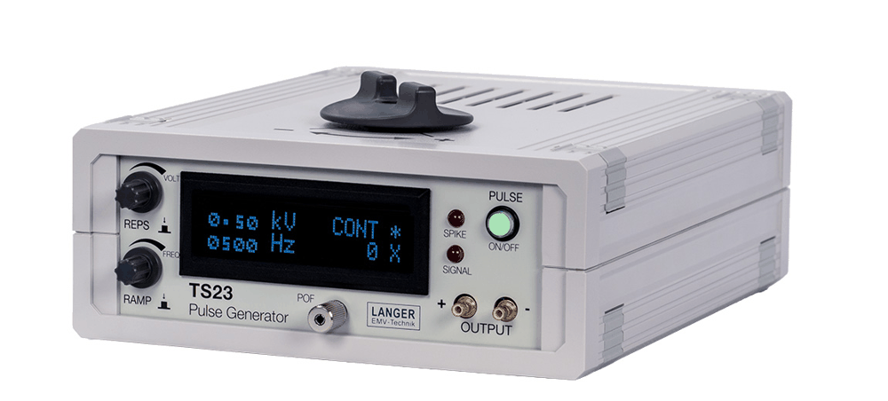
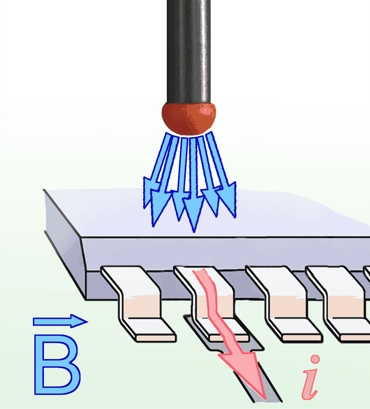
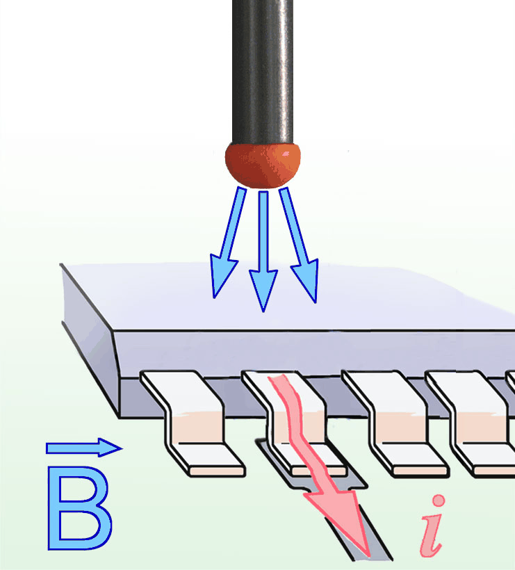
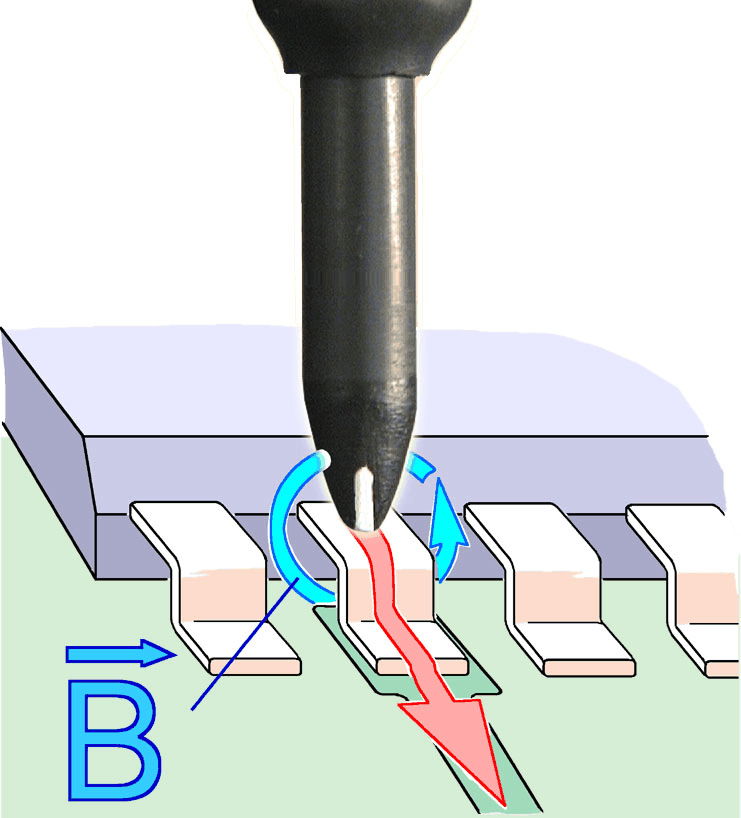
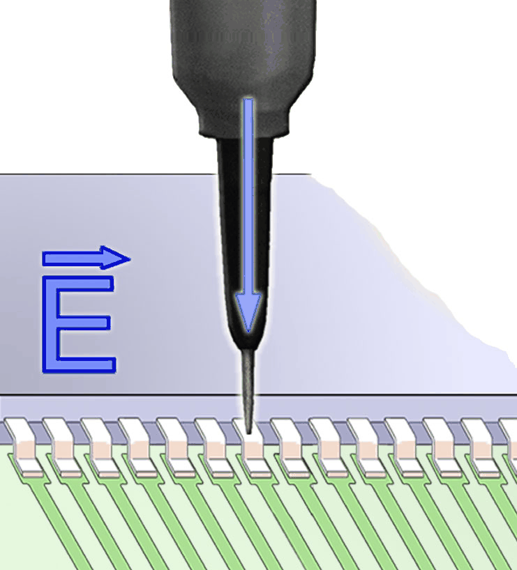
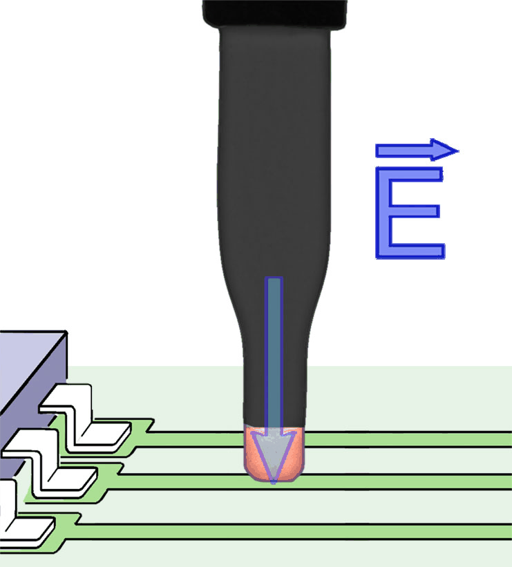
The E2 Set uses the TS 23 pulse generator to investigate PCB and device susceptibility during development or after an immunity test failure. Magnetic, electric and resistive coupling tools help separate the entry path from the sensitive circuit. Adjustable amplitude, polarity and pulse modes let engineers reproduce a failure and evaluate a design change at the workbench. The kit includes a ground plate, differential injectors, S25 optical sensor and coupling accessories.
MARKETS:
CATEGORIES:
TEST STANDARDS:
Select Options/Sizes:

E2 set - Datasheet
SPECIFICATIONS
E2 set - TS 23 PCB Immunity Development System
The E2 Set uses the TS 23 pulse generator to investigate PCB and device susceptibility during development or after an immunity test failure. Magnetic, electric and resistive coupling tools help separate the entry path from the sensitive circuit. Adjustable amplitude, polarity and pulse modes let engineers reproduce a failure and evaluate a design change at the workbench. The kit includes a ground plate, differential injectors, S25 optical sensor and coupling accessories.

Features and application benefits
| Feature | Engineering benefit / use |
|---|---|
| Pulse control | TS 23 offers Continuous, Ramp, Pulse Groups, Boost and External Trigger modes. Amplitude, polarity and repetition frequency are adjustable. |
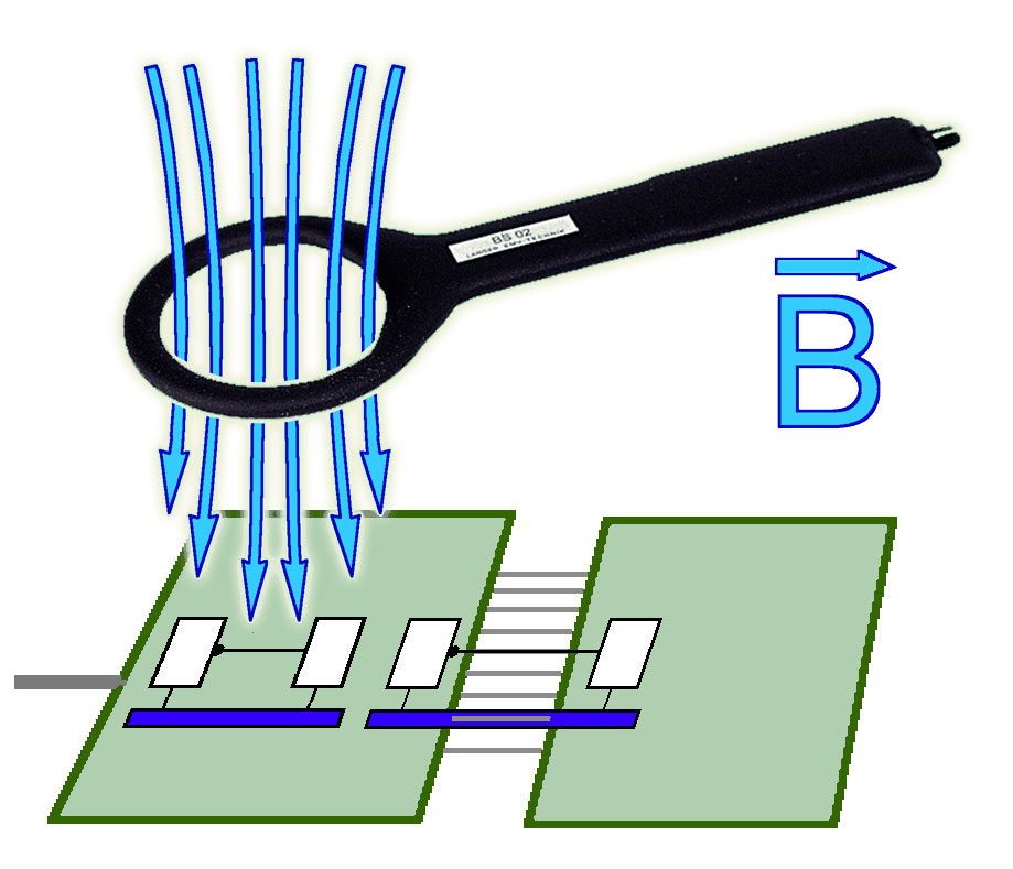
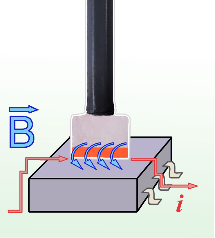
| Coupling methods | Use magnetic or electric field sources for local field injection, and the supplied base adapters, DEA, DE2 and DE6 tools for resistive or differential injection tasks. |
| Optical monitoring | S25 supports DC to 50 Mbps. The TS 23 optical trigger input has its own 5 MHz maximum and 100 ns minimum pulse-width limits. |
| Failure analysis | Identify a repeatable DUT fault, find the entry path, change the design, and repeat the same disturbance conditions to compare susceptibility. |
| TS 23 output and pulse groups | The generator has symmetrical, galvanically isolated outputs. Pulse groups contain 1-50 pulses; the integrated modulator supports pulse-height variations such as a voltage ramp. |
| Pulse-rate counter | An integrated counter uses an optical input to detect signals from the assembly. Distinguish this input from the supplied S25 sensor data-rate specification. |
Technical specifications
| Parameter | Specification |
|---|---|
| TS 23 Pulse Generator / Supply voltage | 24 V / 1 A DC |
| TS 23 Pulse Generator / Pulse parameter / Rise time | 1.5 ns |
| TS 23 Pulse Generator / Pulse parameter / Max. Pulse voltage | 2.2 kV (adjustable) |
| TS 23 Pulse Generator / Pulse parameter / Repetition frequency | 1.5 kHz (adjustable) |
| TS 23 Pulse Generator / Pulse parameter / Polarity | +/- (adjustable) |
| TS 23 Pulse Generator / Pulse parameter / Operating Modes | Continuous, Ramp, Pulse Groups, Boost, External Trigger |
| TS 23 Pulse Generator / Optical input / Optical fiber | 2.2 mm |
| TS 23 Pulse Generator / Optical input / Max. frequency | 5 MHz |
| TS 23 Pulse Generator / Optical input / Min. pulse width | 100 ns |
| TS 23 Pulse Generator / Optical input / Sizes (L x W x H) | (160 x 200 x 75) mm |
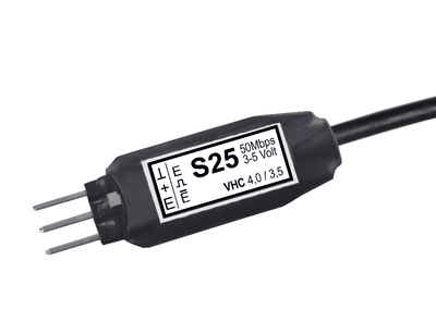
| S25 Optical Sensor / Transmission range | DC ... 50 Mbps |
| S25 Optical Sensor / Optical fibre connector | 2.2 mm |
| S25 Optical Sensor / Supply voltage | (3 - 5) V |
| S25 Optical Sensor / Current input | 30 mA |
| TS 23 pulse description | 12 ns pulse width; 10 V to 2.2 kV amplitude stated in component description |
Included components
| Photo | Qty. | Item | Function / key specifications |
|---|---|---|---|
 |
1x | TS 23 | Pulse Generator Device functionality: / Operating Modes: Continuous, Ramp, Pulse Groups, Boost, External Trigger Pulse parameter / Rise time: 1.5 ns Pulse parameter / Max. Pulse voltage: 2.2 kV (adjustable) Pulse parameter / Polarity: +/- (adjustable) |
| 1x | GP 10 | Ground Plate E2 set | |
| 1x | MA 33-L | Magnetic Base Adapter for Resistive Coupling (left) | |
| 1x | MA 33-R | Magnetic Base Adapter for Resistive Coupling (right) | |
| 1x | DEA | Diff-to-Single-Ended Adapter | |
| 3x | DE2 | Differential Injector | |
| 3x | DE6 | Differential Injector | |
 |
1x | MS 101 | Magnetic Field Probe Weight: 10 g |
 |
1x | BS 02-h | Magnetic Field Source Probe head dimensions: > 5 cm Weight: 18 g |
 |
1x | BS 03-d | Magnetic Field Source Probe head dimensions: (15 x 20 x 3) mm Length of source cable: 16 mm Weight: 24 g Sizes (L x W x H): (146 x 23 x 12) mm |
 |
1x | BS 04DB-d | Magnetic Field Source Probe head dimensions / Inner diameter of coil: 4 mm Probe head dimensions / Weight: 26,5 g Probe head dimensions / Sizes (L x W x H): (148 x 23 x 12) mm |
 |
1x | BS 04DB-h2 | Magnetic Field Source Probe head dimensions / Inner diameter of coil: 4 mm Probe head dimensions / Connector - input: SMB, male, jack Probe head dimensions / Weight: 14 g |
 |
1x | BS 05DU-h2 | Magnetic Field Source Probe head dimensions: diameter ≈ 4 mm Connector - input: SMB, male, jack Weight: 15 g |
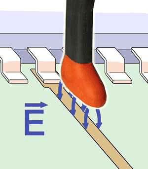 |
1x | ES 01 | E-Field Source |
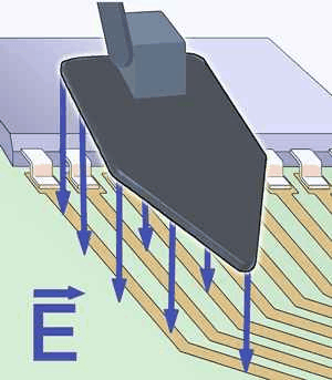 |
1x | ES 02 | E-Field Source |
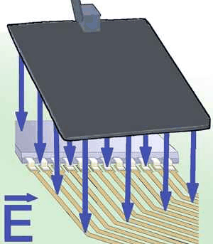 |
1x | ES 05D-h | E-Field Source |
 |
1x | ES 08D-h | E-Field Source |
 |
1x | ES 10D-h | E-Field Source Probe head dimensions: (0.5 x 2) mm Connector: SMB, male, jack Weight: 15 g |
| 1x | NT FRI EU 24V | Power Supply Unit | |
 |
1x | S25 | Optical Sensor (50 Mbps) Transmission range: DC ... 50 Mbps Optical fibre connector: diameter 2.2 mm Supply voltage: 3 V ... 5 V Current input: 30 mA |
 |
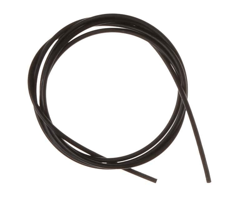
1x | LWL diameter 2.2 mm 1.5 m | Optical Fiber Single 1.5 m Diameter: 2.2 mm diameter Sizes (L x W x H): 1.5 m |
| 1x | E2 acc | Accessories | |
| 1x | E2 case | System Case | |
| 1x | E2 qg | TS 23 set Quick Guide | |
| 1x | E2 m | E2 set User Manual |
Included component specifications
| Component | Parameter | Specification |
|---|---|---|
| TS 23 | Device functionality: / Operating Modes | Continuous, Ramp, Pulse Groups, Boost, External Trigger |
| TS 23 | Pulse parameter / Rise time | 1.5 ns |
| TS 23 | Pulse parameter / Max. Pulse voltage | 2.2 kV (adjustable) |
| TS 23 | Pulse parameter / Polarity | +/- (adjustable) |
| TS 23 | Pulse parameter / Pulse repetition frequency | max. 1.5 kHz (adjustable) |
| TS 23 | Pulse parameter / Connector | SMB |
| TS 23 | Optical input / Optical fiber | 2.2 mm |
| TS 23 | Optical input / Max. frequency | 5 MHz |
| TS 23 | Optical input / Min. pulse width | 100 ns |
| TS 23 | Optical input / Supply voltage | 24 V / 1 A DC |
| TS 23 | Optical input / Weight | 850 g |
| TS 23 | Optical input / Sizes (L x W x H) | (160 x 200 x 75) mm |
| MS 101 | Weight | 10 g |
| BS 02-h | Probe head dimensions | > 5 cm |
| BS 02-h | Weight | 18 g |
| BS 03-d | Probe head dimensions | (15 x 20 x 3) mm |
| BS 03-d | Length of source cable | 16 mm |
| BS 03-d | Weight | 24 g |
| BS 03-d | Sizes (L x W x H) | (146 x 23 x 12) mm |
| BS 04DB-d | Probe head dimensions / Inner diameter of coil | 4 mm |
| BS 04DB-d | Probe head dimensions / Weight | 26,5 g |
| BS 04DB-d | Probe head dimensions / Sizes (L x W x H) | (148 x 23 x 12) mm |
| BS 04DB-h2 | Probe head dimensions / Inner diameter of coil | 4 mm |
| BS 04DB-h2 | Probe head dimensions / Connector - input | SMB, male, jack |
| BS 04DB-h2 | Probe head dimensions / Weight | 14 g |
| BS 05DU-h2 | Probe head dimensions | diameter ≈ 4 mm |
| BS 05DU-h2 | Connector - input | SMB, male, jack |
| BS 05DU-h2 | Weight | 15 g |
| ES 10D-h | Probe head dimensions | (0.5 x 2) mm |
| ES 10D-h | Connector | SMB, male, jack |
| ES 10D-h | Weight | 15 g |
| S25 | Transmission range | DC ... 50 Mbps |
| S25 | Optical fibre connector | diameter 2.2 mm |
| S25 | Supply voltage | 3 V ... 5 V |
| S25 | Current input | 30 mA |
| S25 | Sizes (L x W x H) | (34 x 10 x 6) mm |
| LWL diameter 2.2 mm 1.5 m | Diameter | 2.2 mm diameter |
| LWL diameter 2.2 mm 1.5 m | Sizes (L x W x H) | 1.5 m |
Application and kit views
| Image | What it shows |
|---|---|
 |
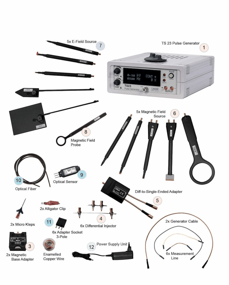
E2 set - Scope of Delivery |
 |
E2 set - Scope of Delivery with Product Designation |
System requirements and ordering notes
TS 23 included; 24 V / 1 A DC. A powered DUT and a way to observe its functional response are required. The tools support engineering diagnosis; they do not replace the complete standardized compliance test setup.
Recommended products and accessories
| Photo | Product | Specifications / purpose | Ordering |
|---|---|---|---|
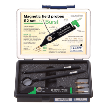 |
S2 set | Active and passive H-field sensing; MSA 02 with 3 heads, MS 101 and MS 102U. One AAA battery is required for MSA 02. Langer recommends S2 for E2; confirm the receiver arrangement because the supplied S2 sheet describes SGZ 21 operation. | Optional set; not included |
Datasheets
| Document | |
|---|---|
| E2 set - Datasheet | View PDF |
Practical questions
| Question | Answer |
|---|---|
| What is this product best suited to? | Choose adjustable pulse modes and more coupling tools for detailed failure analysis. |
| What supporting equipment is needed? | TS 23 included; 24 V / 1 A DC. A powered DUT and a way to observe its functional response are required. The tools support engineering diagnosis; they do not replace the complete standardized compliance test setup. |
| Does this establish compliance with IEC 61000-4-4 or IEC 61000-4-2? | These are development and diagnostic tools. Relating a local disturbance to an EFT/burst or ESD failure helps troubleshooting; formal compliance requires the applicable standardized generator, coupling method, test setup and procedure. |
PCB immunity selection guide
Compare generation, coupling and detection tools. The kit pictures identify the complete sets. Product links below use the planned Absolute EMC product pages.
| Kit | Product / function | Key distinction | Required pulse source / power |
|---|---|---|---|
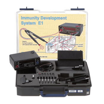 |
E1 set Integrated generation and local E/H-field troubleshooting |
Approx. 0-1500 V pulses | 2 ns rise / 10 ns tail | 4 H-field + 5 E-field sources | 10 Mbps optical sensor | SGZ 21 included; 12 V / 200 mA |
|
E2 set Programmable pulse generation and differential injection |
Up to 2.2 kV adjustable | 1.5 ns rise | Adjustable 1.5 kHz repetition | Both polarities | 50 Mbps optical sensor | TS 23 included; 24 V / 1 A DC |
|
S2 set Transient magnetic-field sensing |
Active + passive H-field probes | 3 MSA 02 heads | Optical signal transfer | MSA 02: 1 AAA battery | SGZ 21 receiver documented; confirm E2 receiver arrangement |
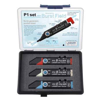 |
P1 set Battery-powered E/H-field injection |
3 generators: P11 + P12 + P21 | Approx. 1 mT H-field / 100 kV/m E-field | Single pulse or 5 kHz | 1.5 V AAA | 1.5 V AAA supply; single pulse / 5 kHz |
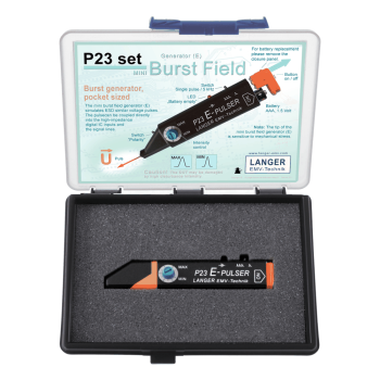 |
P23 set Fine-tip capacitive pulse injection |
1.2 kV generator voltage | 10 pF coupling | 1.8-10 ns rise | Single pulse or 5 kHz | 1.5 V AAA | 1.5 V AAA supply; single pulse / 5 kHz |
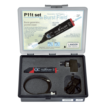 |
P11t set TTL-synchronized magnetic pulse injection |
Approx. 1 mT | 5 V TTL SMB trigger | Single pulse to 10 kHz | 3 us trigger delay | 6.5-15 V supply | 6.5-15 V supply; power supply included |
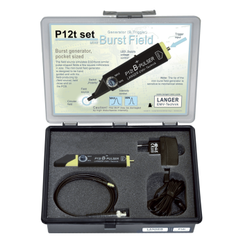 |
P12t set TTL-synchronized clamp-style magnetic coupling |
Approx. 1 mT | Coupling-clamp tip | 5 V TTL SMB trigger | Single pulse to 10 kHz | 3 us delay | 6.5-15 V supply; power supply included |
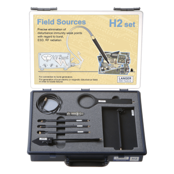 |
H2 set External-generator E/H-field coupling |
6 field sources: 3 H + 3 E | Up to 4.4 kV source supply | External EFT/burst generator required | External EFT/burst generator; source limit 4.4 kV |
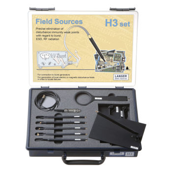 |
H3 set Extended external-generator E/H-field coupling |
9 field sources: 4 H + 5 E | High-voltage SMB connections | SHV or Fischer cable choice | External generator required | External EFT/burst generator; observe each source rating |
 |
PT4 set Potential-free pulse injection plus E/H-field coupling |
4.5 kV maximum burst input | 1:1 transformer | 500 V output dielectric strength | H- and E-field sources | External EFT/burst generator; transformer maximum 4.5 kV |
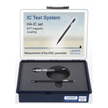 |
H4-IC set Small-area magnetic field coupling |
Up to 200 mT | 2.54 mm2 resolution | 1.8 mm diameter head | 0-66 MHz | 4 kV maximum burst | External EFT/burst generator; 4 kV maximum burst input |
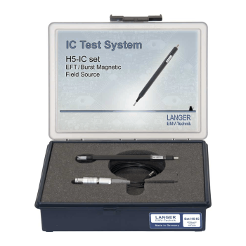 |
H5-IC set Magnetic field coupling with BS 06DU-s |
Up to 150 mT | 5 x 6 mm head | 0-560 MHz | 4 kV maximum burst | 15 g source | External EFT/burst generator; 4 kV maximum burst input |
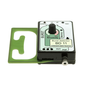 |
BD 11 Cable-transient detection and event indication |
Adjustable sensitivity | LED + relay + optical outputs | 20 m maximum fiber | 2 AAA batteries | 88 x 85 x 32 mm | Two 1.5 V AAA batteries |
OTHER PRODUCTS IN THE SAME CATEGORY:
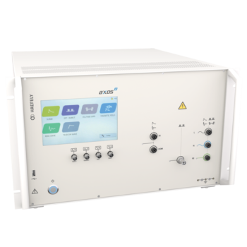
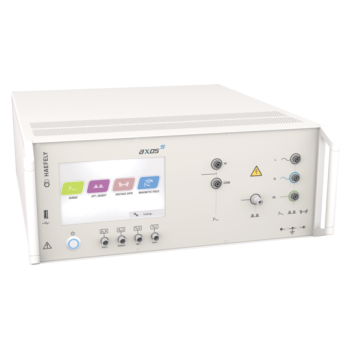
Axos 5 - Compact 5kV EFT, Surge, Dips/Drops
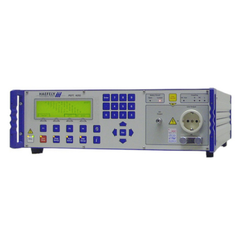
PEFT 8010 EFT/Burst Test System up to 7.3 kV
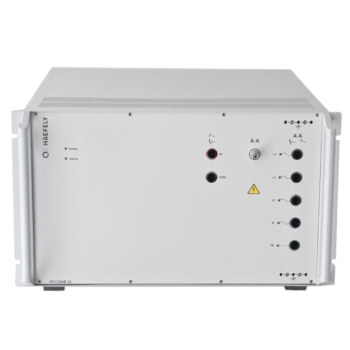
FP-COMB 32, Combined Automatic 3-Phase Coupling / Decoupling Network
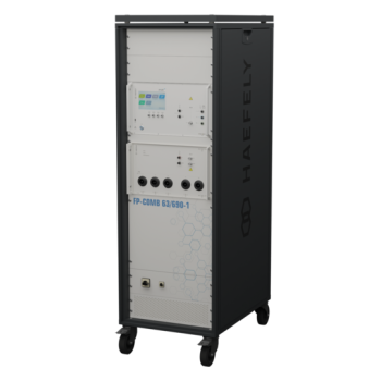
FP-COMB 63 / 125 / 200 A - 690 V AC Coupling / Decoupling Networks
FP-COMB 63 / 125 / 200 A - 1500 V DC Coupling / Decoupling Networks
FP-COMB 63 / 125 / 200 A - 690 V AC + 1500 V DC Test Networks

Langer E1 set | PCB Immunity Development System
Langer E2 set | TS 23 PCB Immunity Development System
ESD Test Table Kit

Langer P1 set | Mini Burst Field Generator Set

Langer S2 set | Magnetic Field Probe Set for Immunity Analysis

Langer P23 set | Mini Burst E-Field Generator Set

Langer P11t set | Triggered Mini Burst Magnetic Field Generator
IP4B - EFT/Burst Capacitive Coupling Clamp

Langer P12t set | Triggered Mini Burst Magnetic Coupling Generator

Langer H2 set | EFT/Burst Electric and Magnetic Field Source Set

Langer H3 set | Extended EFT/Burst Field Source Set

Langer PT4 set | EFT/Burst Transformer and Field Source Set

Langer H4-IC set | Localized EFT/Burst Magnetic Field Source Set