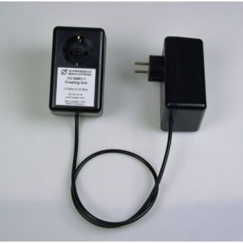
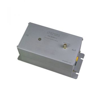
CU 50561-1, Coupling Unit , acc. EN 50561-1
- The coupling unit for measurements at powerline transmission devices.
- Acc. standard EN-50561-1
- Combined with two-line impedance stabilization networks (LISN)
PARTNER:
MARKETS:
CATEGORIES:
TEST STANDARDS:

Overview PLC Measurement-System EN 50561-1
Data Sheet
SPECIFICATIONS
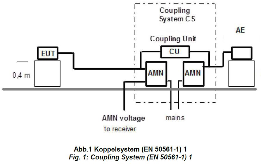
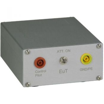
CU 50561-1, Coupling Unit, acc. EN 50561-1Description The coupling unit CU 50561-1 belongs to the equipment for measurements at powerline transmission devices. The specifications for the measurements at PLC devices are included within the standard EN-50561-1. Combined with two-line impedance stabilization networks (LISN) the coupling unit provides a coupling system that guarantees defined conditions for the measurement. To be able to measure the interference emission of a PLC modem especially at its maximum transmit level a transmission line with a defined RF attenuation has to be provided. For this purpose, two-line impedance stabilization networks (LISN) as well as one coupling unit are required. The LISN provides mains to the EuT respectively the AE ports individually, see fig. 1 for an overview.
The coupling unit only bypasses the high-frequency PLC signals with a defined attenuation. Combined with the LISNs the coupling system performs the following tasks:
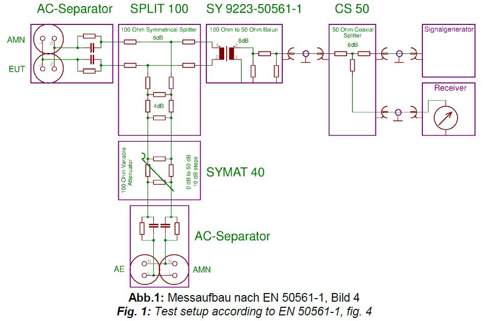
The coupling unit described in this document is built according to the standard. To verify the properties of the unit the attenuation characteristic has to be measured in a symmetrical 25 Ω system. The typical response characteristics is shown in fig. 2.Each protective earth, phase and neutral is connected to each other in every connector box. The protective earth between the different connector boxes is not connected!
PDF Overview PLC Measurement-System EN 50561-1
|
||||||||||||||||||||||||||||||
OTHER PRODUCTS IN THE SAME CATEGORY:
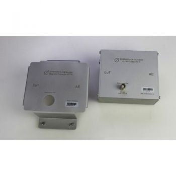
8158 Mag Base, Magnetic Cover for ISN 8158 to attach ISN to steel wall
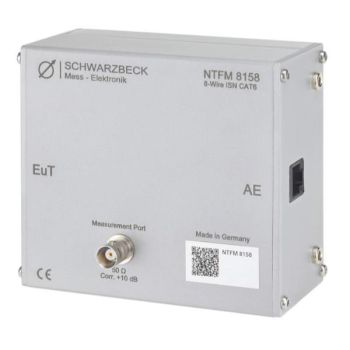
NTFM 8158, ISN for unshielded Cat 6 lines, Acc CISPR 32
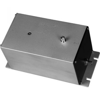
CDN ISN S1 BNC, Coupling Decoupling Network
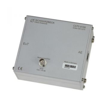
CAT5 8158, ISN for unshielded Cat 5 lines, Acc CISPR 32
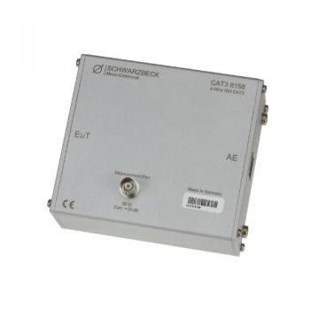
CAT3 8158, ISN for unshielded Cat 3 lines, Acc CISPR 32
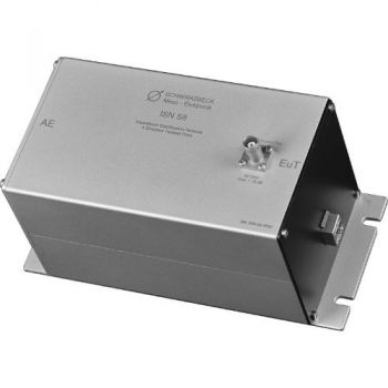
ISN S8, ISN for Shielded Telecom lines, Acc CISPR 32 - Discontinued
ISN S1, ISN for Coax Acc CISPR 32 - Discontinued
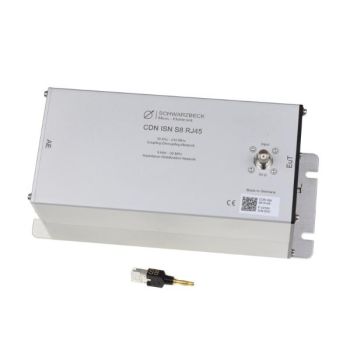
CDN ISN S8 RJ45, CDN/ISN for Shielded Telecom lines, Acc IEC 6100-4-6/CISPR 32
ISN 50561-1, ISN for PLC measurement, acc. EN 50561-1
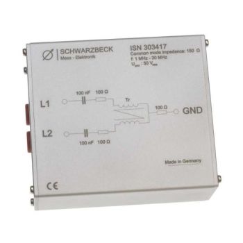
ISN 303417, ISN for 150 Ohm Common Mode Measurements
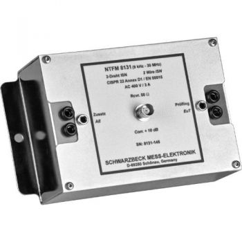
NTFM 8131, ISN for 2 unshielded Unsymetrical lines, Acc CISPR 32
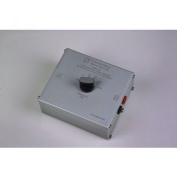
SYMAT 40, Symmetrical Step Attenuator, 100 Ohms acc. EN 50561-1
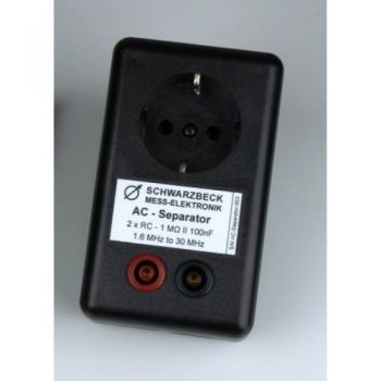
AC Separator, acc. EN 50561-1
CU 50561-1, Coupling Unit , acc. EN 50561-1
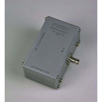
SY 9223-50561-1, Symmetrical Transformer, 50 to 100 Ohms acc. EN 50561-1
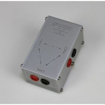
SPLIT 100, 2 way splitter, 100 Ohms acc. EN 50561-1
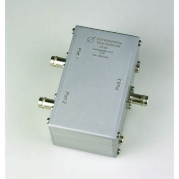
CS-50, 2 way splitter, 50 Ohms acc. EN 50561-1
PILOT ISN, 150 kHz - 30 MHz, 1.4A, PLC
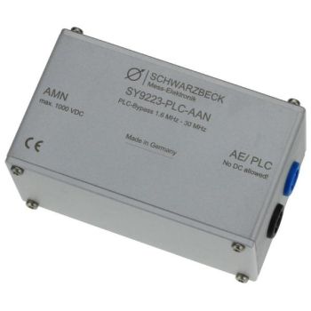
SY 9223-PLC-AAN, PLC bypass

