ISN S8, ISN for Shielded Telecom lines, Acc CISPR 32 - Discontinued
Discontinued. See CDN ISN S8 RJ45
- Impedance Stabilisation Network (ISN)
- acc. CISPR 22 Ed.5.5:2006, (CISPR 32)
- CISPR 22, CISPR 32 Annex G.11 and EN 55022 Annex D figure D.11
- Is capable to provide 1000 MBit/s (Gigabit-Ethernet, 1000BASE-T).
PARTNER:
MARKETS:
CATEGORIES:
TEST STANDARDS:

Data Sheet
SPECIFICATIONS
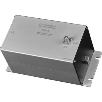
ISN S8, ISN for Shielded Telecom lines, Acc CISPR 32The ISN S8 can be used to measure the conducted voltage emissions of telecommunication and data processing equipment. It is designed to measure the coaxial line. It is based on IEC/CISPR 22 and the related national standards. The special circuitry and design are described in CISPR 22, and EN 55022 Annex D figure D.9. The ISN must provide sufficient decoupling from the equipment under test (EuT) to the auxiliary equipment (AE) which could be a communication device or a kind of load. The measured conducted voltage is coupled out to the BNC connector on top of the ISN S1. An EMI receiver or spectrum analyzer is most commonly used for a measuring instrument. The ISN S8 can also be used in the other direction to inject conducted radio frequency disturbance into the shield of communication wires. This method is described in IEC/EN 61000-4-6. If the ISN S8 is used for injection it is also referred to as a coupling decoupling network (CDN). The ISN S8 is capable to provide 1000 MBit/s (Gigabit-Ethernet, 1000BASE-T). A cable of the suitable cable category is built-in and is wired according to TIA-568A/B.
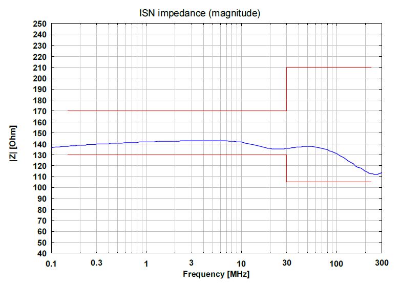
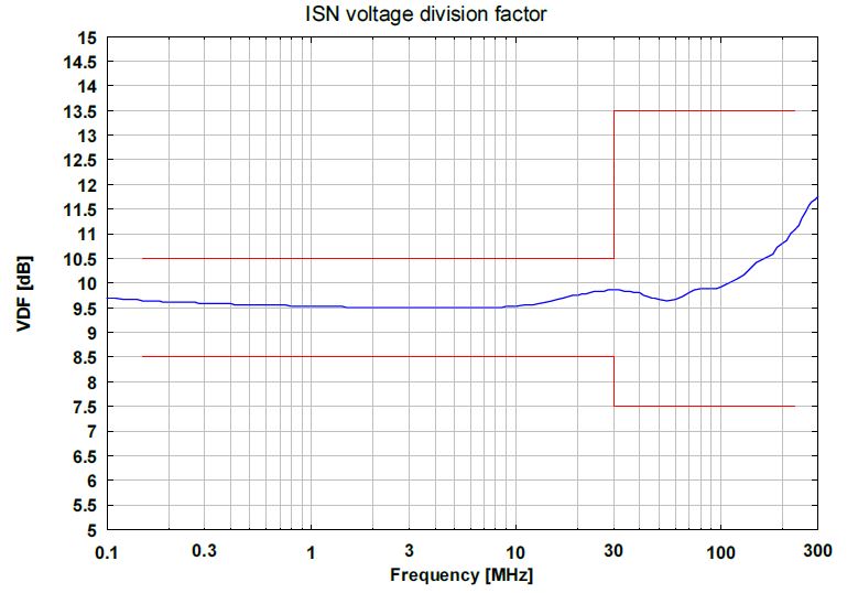
Application: The measurement is described in detail in CISPR 22, CISPR 32, and EN 55022 chapter 8. The equipment under test must be connected to the EuT-port. The auxiliary equipment has to be connected to the AEport. The EMI-receiver or spectrum analyzer has to be connected to the BNC port of the ISN S8 using a coaxial line. Fixture lugs at the bottom plate of the ISN S8 allow fixing the device with screws to the cabin wall. As CISPR 22 defines the limits for conducted emissions in a 150 Ω system there is a 100 Ω resistor in series to the BNC connector. In combination with the 50 Ω input resistance of the measurement device a voltage division factor of 1:3 follows. On a logarithmic scale, this is equal to 9.5 dB. The measured voltages across 50 Ω, therefore, have to be multiplied with 3, or in other words, a correction of 9.5 dB must be added. This value of 9.5 dB is called the voltage division factor (VDF). This VDF is slightly frequency-dependent. For very precise measurements it is recommended to take the exact frequency-dependent VDF into account (see calibration certificate). The shield or outer cable is defined as the common-mode point for the EuT connector of ISN/CDN equipment. To be able to do a measurement (i.e. the impedance of the ISN or to normalize the voltage division factor) at this measuring point an adapter is needed. This adapter can be purchased separately and is needed to connect the shield of the RJ45 socket to the measurement device. It is called “CA ISN S8” where the U-section can be attached to the shield of the RJ45 socket at the EuT part of the ISN and the 4 mm plug matches into the 50 Ω to 150 Ω adapter SR100-6W which can be purchased separately as well. It is given that when putting the ISN S8 and the SR100-6W together the normative distance of 30 mm between the front surfaces automatically is fulfilled. To enable you to connect your own measurement equipment the CA ISN S8 consists of two parts and can be taken apart very easily. A 4 mm plug provides the connection to the SR100-6W keeping the given distance. If you want to use the ISN S8 as a CDN the use of the adapter “CA ISN S8” and the 50 Ω to 150 Ω adapter “SR100-6W” is mandatory. The measurement setup is described within the norm IEC/EN 61000-4-6 picture 8c.
|


OTHER PRODUCTS IN THE SAME CATEGORY:
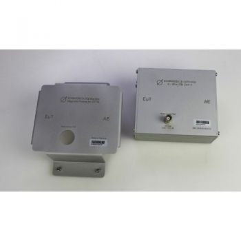
8158 Mag Base, Magnetic Cover for ISN 8158 to attach ISN to steel wall
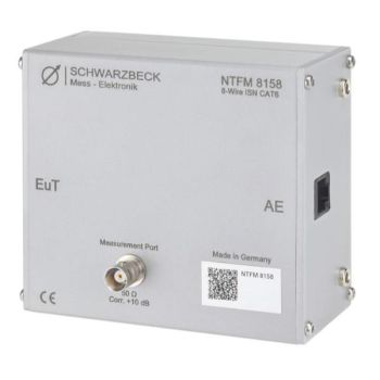
NTFM 8158, ISN for unshielded Cat 6 lines, Acc CISPR 32
CDN ISN S1 BNC, Coupling Decoupling Network
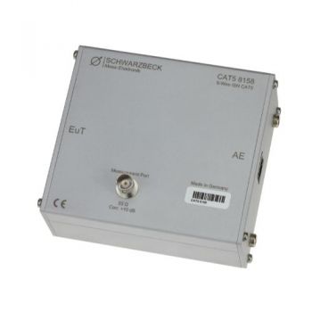
CAT5 8158, ISN for unshielded Cat 5 lines, Acc CISPR 32
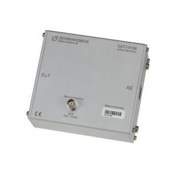
CAT3 8158, ISN for unshielded Cat 3 lines, Acc CISPR 32
ISN S8, ISN for Shielded Telecom lines, Acc CISPR 32 - Discontinued
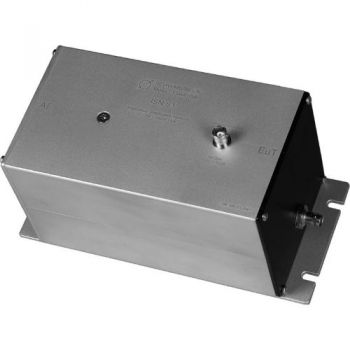
ISN S1, ISN for Coax Acc CISPR 32 - Discontinued
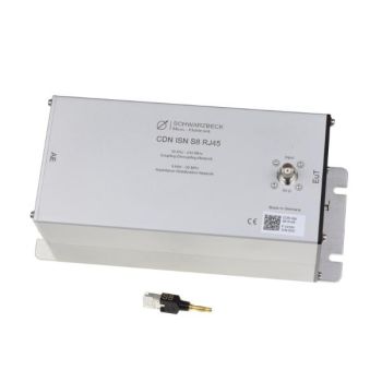
CDN ISN S8 RJ45, CDN/ISN for Shielded Telecom lines, Acc IEC 6100-4-6/CISPR 32
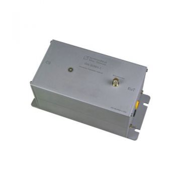
ISN 50561-1, ISN for PLC measurement, acc. EN 50561-1
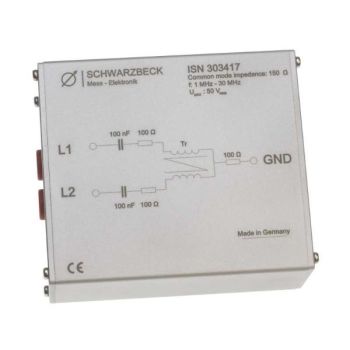
ISN 303417, ISN for 150 Ohm Common Mode Measurements
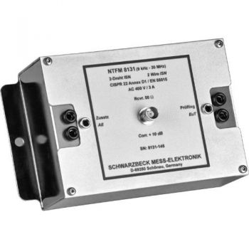
NTFM 8131, ISN for 2 unshielded Unsymetrical lines, Acc CISPR 32
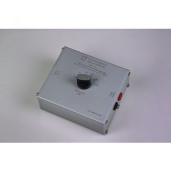
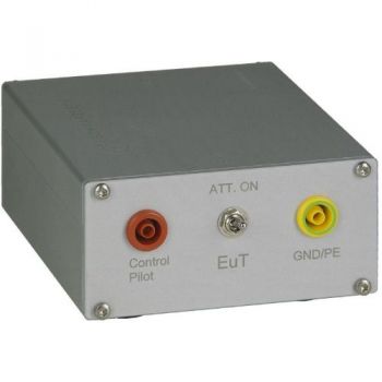
SYMAT 40, Symmetrical Step Attenuator, 100 Ohms acc. EN 50561-1
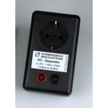
AC Separator, acc. EN 50561-1
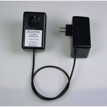
CU 50561-1, Coupling Unit , acc. EN 50561-1
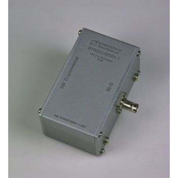
SY 9223-50561-1, Symmetrical Transformer, 50 to 100 Ohms acc. EN 50561-1
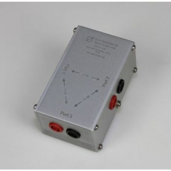
SPLIT 100, 2 way splitter, 100 Ohms acc. EN 50561-1
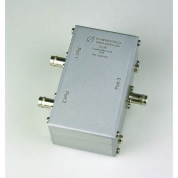
CS-50, 2 way splitter, 50 Ohms acc. EN 50561-1
PILOT ISN, 150 kHz - 30 MHz, 1.4A, PLC
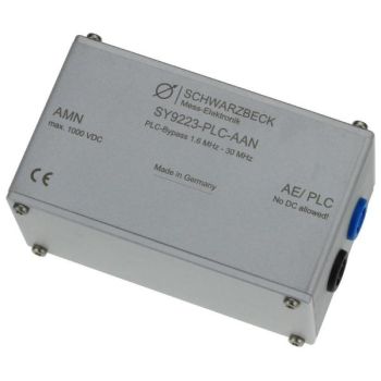
SY 9223-PLC-AAN, PLC bypass

