ISN 50561-1, ISN for PLC measurement, acc. EN 50561-1
- Impedance stabilization network (ISN)
- For measurements of asymmetrical disturbance voltage of power line communication equipment
- Acc. standard EN 50561-1:2012, Annex B, Figure B.1.
PARTNER:
MARKETS:
CATEGORIES:
TEST STANDARDS:

Overview PLC Measurement-System EN 50561-1
Data Sheet
SPECIFICATIONS
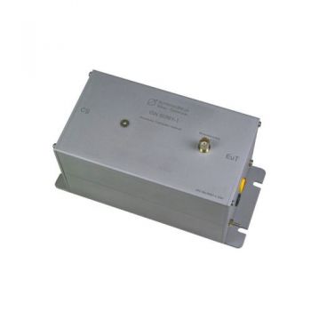
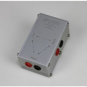
ISN 50561-1, ISN for PLC measurement, acc. EN 50561-1Description ISN 50561-1 is an impedance stabilization network (ISN) for measurements of asymmetrical disturbance voltage of power line communication equipment. This ISN is built according to the standard EN 50561-1, Annex B, Figure B.1. An impedance stabilization network has the following purposes:
The measurement setup to obtain the conducted asymmetrical disturbance voltage is explained in the standard EN 50561-1, chapter 9.4. Figure 6 shows the setup. To minimize the chance of measurement errors the additional possibilities to ground the ISN 50561-1 may be used. Normally it should be sufficient to put the not-painted bottom of the ISN on the reference ground plane. If a vertical measurement setup is required, the ISN can be mounted at the bracket located at the bottom using four M6 screws.
PDF Overview PLC Measurement-System EN 50561-1
|
OTHER PRODUCTS IN THE SAME CATEGORY:
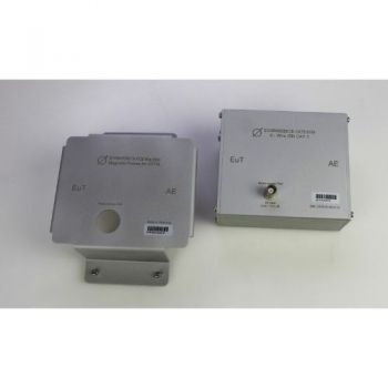
8158 Mag Base, Magnetic Cover for ISN 8158 to attach ISN to steel wall
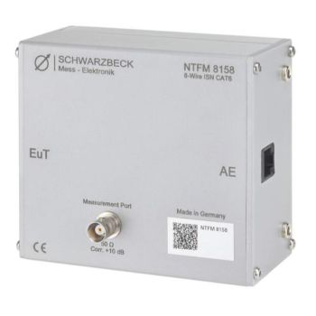
NTFM 8158, ISN for unshielded Cat 6 lines, Acc CISPR 32
CDN ISN S1 BNC, Coupling Decoupling Network
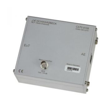
CAT5 8158, ISN for unshielded Cat 5 lines, Acc CISPR 32
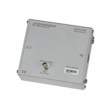
CAT3 8158, ISN for unshielded Cat 3 lines, Acc CISPR 32
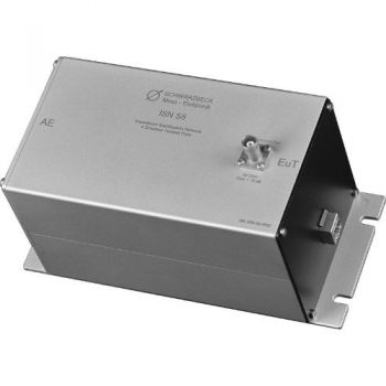
ISN S8, ISN for Shielded Telecom lines, Acc CISPR 32 - Discontinued
ISN S1, ISN for Coax Acc CISPR 32 - Discontinued
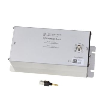
CDN ISN S8 RJ45, CDN/ISN for Shielded Telecom lines, Acc IEC 6100-4-6/CISPR 32
ISN 50561-1, ISN for PLC measurement, acc. EN 50561-1
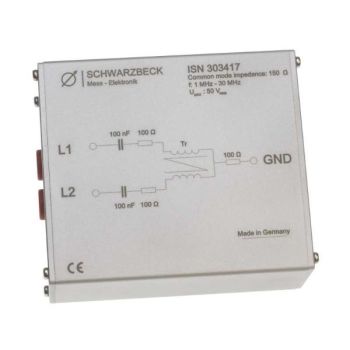
ISN 303417, ISN for 150 Ohm Common Mode Measurements
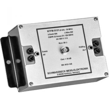
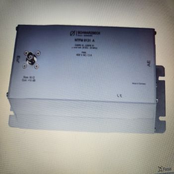
NTFM 8131, ISN for 2 unshielded Unsymetrical lines, Acc CISPR 32
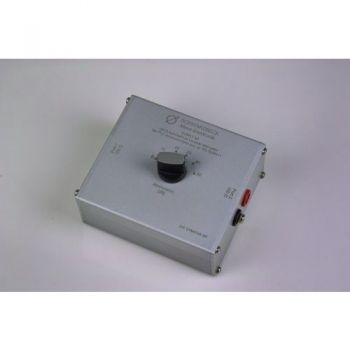
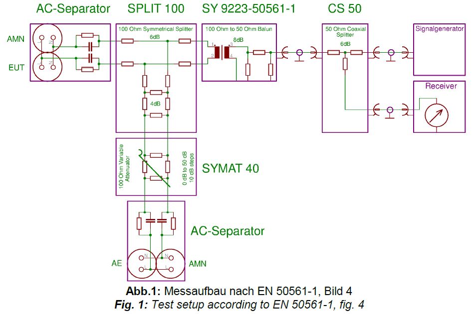
SYMAT 40, Symmetrical Step Attenuator, 100 Ohms acc. EN 50561-1
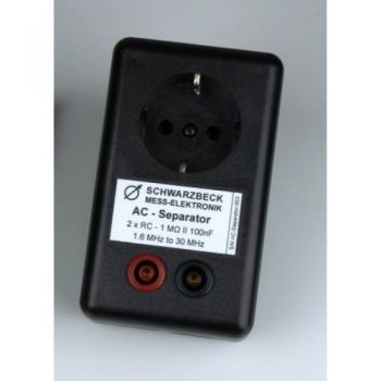
AC Separator, acc. EN 50561-1
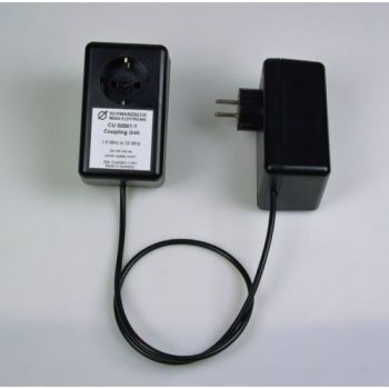
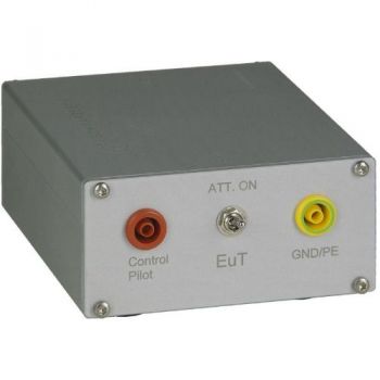
CU 50561-1, Coupling Unit , acc. EN 50561-1
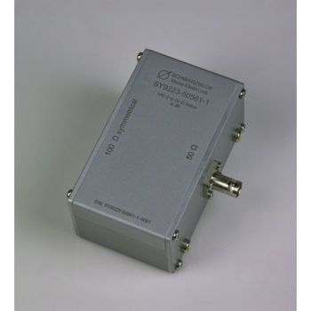
SY 9223-50561-1, Symmetrical Transformer, 50 to 100 Ohms acc. EN 50561-1
SPLIT 100, 2 way splitter, 100 Ohms acc. EN 50561-1
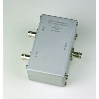
CS-50, 2 way splitter, 50 Ohms acc. EN 50561-1
PILOT ISN, 150 kHz - 30 MHz, 1.4A, PLC
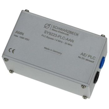
SY 9223-PLC-AAN, PLC bypass

