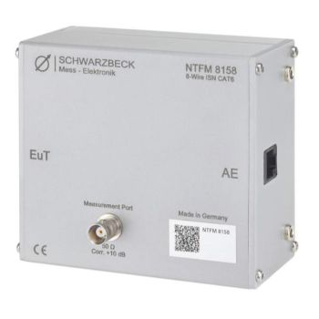
NTFM 8158, ISN for unshielded Cat 6 lines, Acc CISPR 32
- Impedance Stabilisation Network (ISN)
- acc. CISPR 22 Ed.5.5:2006, (CISPR 32)
- Unshielded twisted pairs (UTP) or communication ports
- With 2, 4, 6, or 8 wires
PARTNER:
MARKETS:
CATEGORIES:
TEST STANDARDS:

Data Sheet
SPECIFICATIONS
NTFM 8158, ISN for unshielded Cat 6 lines, Acc CISPR 32The ISN NTFM 8158 allows performing common mode disturbance voltage measurements on unshielded twisted pairs (UTP) or communication ports with 2, 4, 6, or 8 wires according to CISPR 22:2005 or EN 55022:2006. The Equipment Under Test (EuT) or Auxiliary Equipment (AE) can be connected using the RJ-45 sockets. The pin assignment follows EIA/TIA-T568A/B. The electrical circuit of NTFM 8158 is designed according to CISPR 22 Edition 5.2, figure D.3. The ISN does not influence the transmission quality up to gigabit Ethernet. The ISN-device NTFM 8158 provides a longitudinal conversion loss of typically 75 dB at the EuT port and allows for the measurement of CAT6 devices. There are two further ISN available for measurements of CAT5 devices (CAT5 8158) and CAT3 devices (CAT3 8158) respectively. In addition to the measurement of disturbance voltage, the NTFM 8158 allows performing measurements of conducted immunity acc. CISPR 24 or EN 55024 up to 80 MH. An additional 50 Ω to 150 Ω adapter (EAB8 50-150) acc. IEC 61000-4-6 is required. This adapter can easily be mounted to the NTFM 8158 and is available as an option. The specification of NTFM 8158 is fully compliant with CISPR 22 Ed. 5.2 and verified according to methods described in CISPR 16-1-2, Annex E.
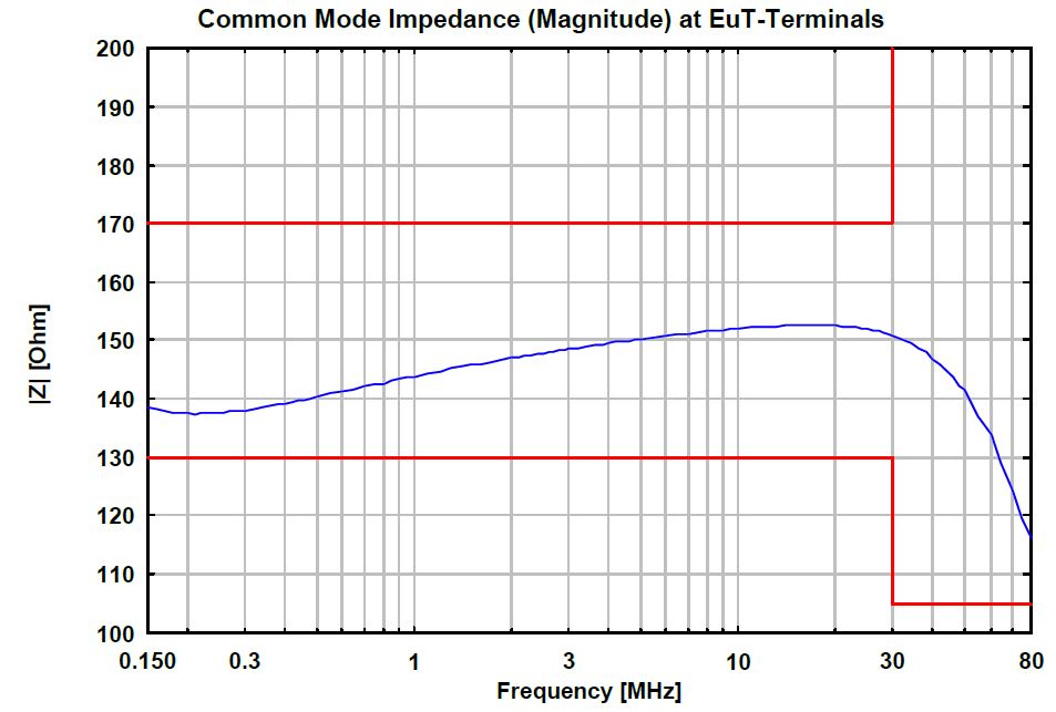
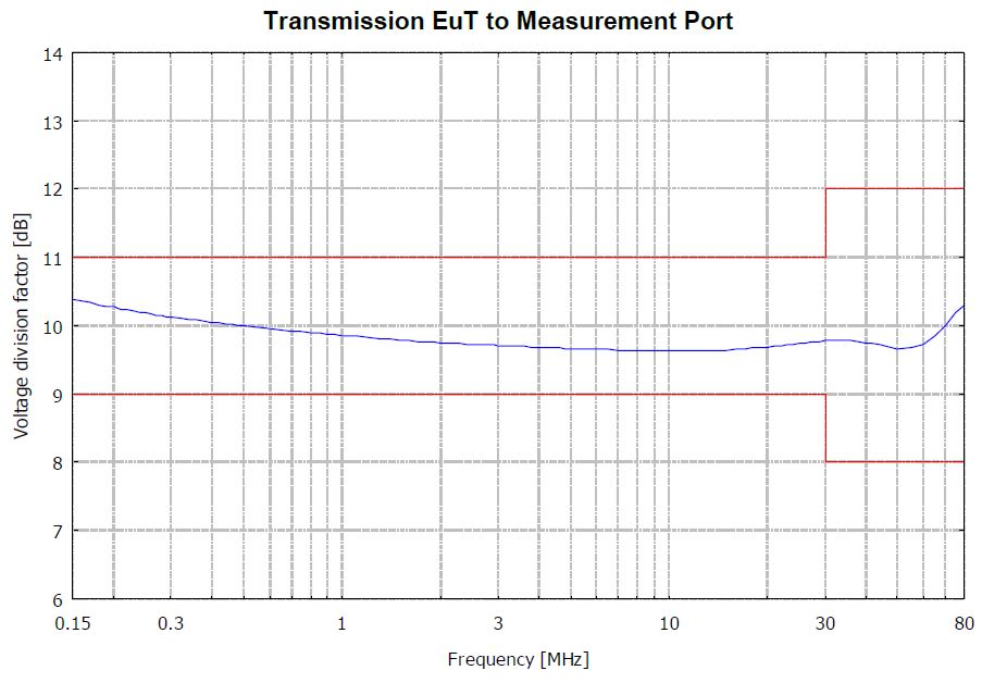
Application: The telecommunication port of the device under test must be connected to the NTFM 8158 EuT-port. The CAT5 8158 provides the asymmetrical port termination of the EuT. Auxiliary Equipment (AE) which has to be operated together with the device under test must be connected to the AE-port of NTFM 8158. The data communication is based on differential mode voltages on pairs of wires. If the virtual null in the electrical middle of the voltages shifts compared to reference ground the magnitude of this shift is called the asymmetrical disturbance voltage or the common-mode voltage. This voltage is decoupled to the BNC-connector to be measured with a receiver. The nominal voltage division factor is 10 dB, i.e. the reading of the voltage at a 50 Ω receiver has to be increased by 10 dB. This results into the disturbance voltage. The LCL describes the conversion of the wanted differential mode data signal along a transmission line into an unwanted common-mode signal. The common-mode signal could be radiated and might cause disturbance field strength. The test setup is described in CISPR 22 in more detail. Special attention must be paid to low inductive grounding, i.e. grounding suitable for radio frequencies. This is achieved by placing the aluminum housing of the NTFM 8158 directly on the reference ground plane. The EuT cable and the AE cable must not be installed close or parallel to each other to avoid unwanted coupling between them.
|


OTHER PRODUCTS IN THE SAME CATEGORY:
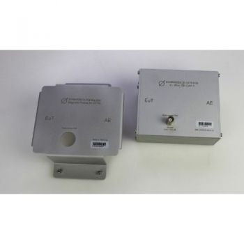
8158 Mag Base, Magnetic Cover for ISN 8158 to attach ISN to steel wall
NTFM 8158, ISN for unshielded Cat 6 lines, Acc CISPR 32
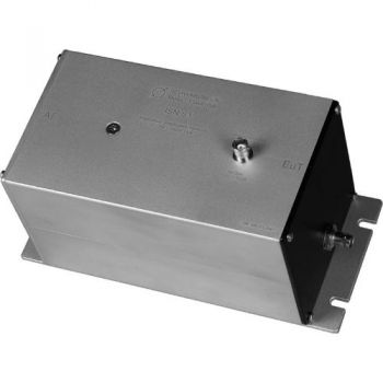
CDN ISN S1 BNC, Coupling Decoupling Network
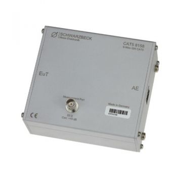
CAT5 8158, ISN for unshielded Cat 5 lines, Acc CISPR 32
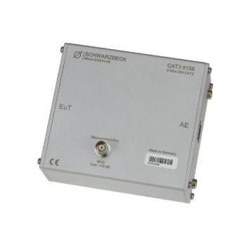
CAT3 8158, ISN for unshielded Cat 3 lines, Acc CISPR 32
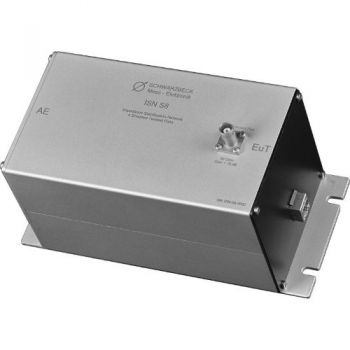
ISN S8, ISN for Shielded Telecom lines, Acc CISPR 32 - Discontinued
ISN S1, ISN for Coax Acc CISPR 32 - Discontinued
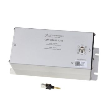
CDN ISN S8 RJ45, CDN/ISN for Shielded Telecom lines, Acc IEC 6100-4-6/CISPR 32
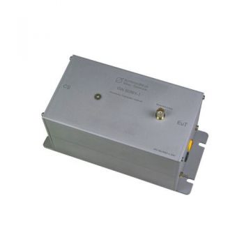
ISN 50561-1, ISN for PLC measurement, acc. EN 50561-1
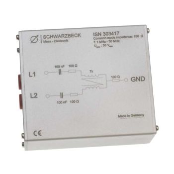
ISN 303417, ISN for 150 Ohm Common Mode Measurements
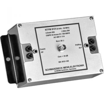
NTFM 8131, ISN for 2 unshielded Unsymetrical lines, Acc CISPR 32
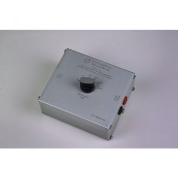
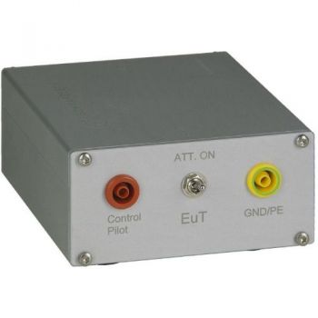
SYMAT 40, Symmetrical Step Attenuator, 100 Ohms acc. EN 50561-1
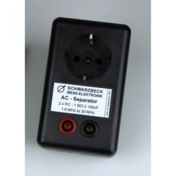
AC Separator, acc. EN 50561-1
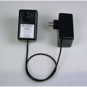
CU 50561-1, Coupling Unit , acc. EN 50561-1
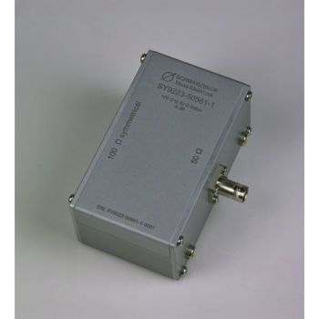
SY 9223-50561-1, Symmetrical Transformer, 50 to 100 Ohms acc. EN 50561-1
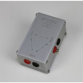
SPLIT 100, 2 way splitter, 100 Ohms acc. EN 50561-1
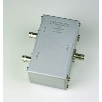
CS-50, 2 way splitter, 50 Ohms acc. EN 50561-1
PILOT ISN, 150 kHz - 30 MHz, 1.4A, PLC
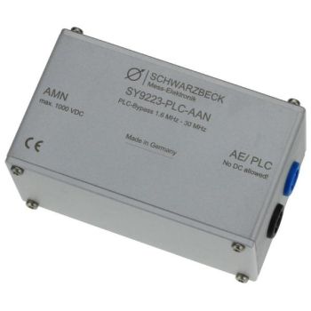
SY 9223-PLC-AAN, PLC bypass

