ISN 50561-3 - Impedance Stabilization Network
- Impedance stabilization network (ISN)
- For measurements of unsymmetrical disturbance voltage on equipment for power line communication (PLC)
- Acc. to EN 50561-3, Annex B.
PARTNER:
MARKETS:
CATEGORIES:
TEST STANDARDS:

Data Sheet
SPECIFICATIONS
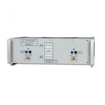
ISN 50561-3 - Impedance Stabilization NetworkISN 50561-3 is an impedance stabilization network (ISN) for measurements of unsymmetrical disturbance voltage on equipment for power line communication (PLC). This ISN is built according to the standard EN 50561-3, Annex B.
Instructions for use: The Schwarzbeck ISN-50561-3 is a measurement network that provides defined impedance at high frequencies across the power feed at the point of measurement of the terminal voltage, it also provides isolation of the circuit under test from the ambient noise on the power lines. The device also provides a defined coupling path between EuT and AE. Important! Connect the ISN 50561-3 to protecting earth BEFORE applying any voltage to it! For this purpose, you can use the screw terminals at the front panel and the aluminum brackets at the rear side of the device. Due to high capacities leakage, currents can occur. Thus it is not possible to use a residual current operated circuit breaker. It is recommended to use an isolating transformer. The supply voltage has to be applied at the back panel of the device by using the Schuko connector. Important! The operator has to make sure that the maximum current is limited to 16 A at the supply side. There is no fuse built into ISN 50561-3 to protect the device under test! The equipment under test (EuT) and the associated equipment (AE) have to be connected to the 4 mm safety laboratory jacks at the front panel. The maximum current that can be drawn of EuT and AE is 16 A in sum. The maximum voltage that can be applied is 250 VAC. The input for the power supply is located at the back panel and provides a hard-wired connection cable with a Schuko plug. One of the coaxial RF outputs has to be connected to the EMI measurement receiver using a BNC coaxial cable. The path that is actually not measured must be terminated with 50 Ω.
|
OTHER PRODUCTS IN THE SAME CATEGORY:
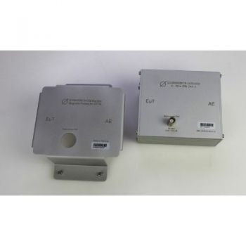
8158 Mag Base, Magnetic Cover for ISN 8158 to attach ISN to steel wall
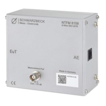
NTFM 8158, ISN for unshielded Cat 6 lines, Acc CISPR 32
CDN ISN S1 BNC, Coupling Decoupling Network
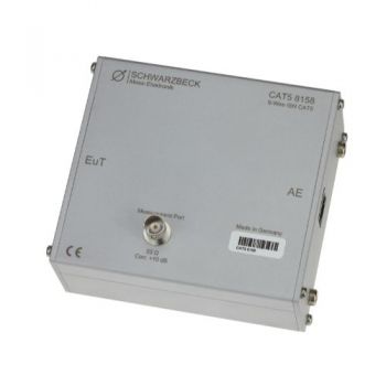
CAT5 8158, ISN for unshielded Cat 5 lines, Acc CISPR 32
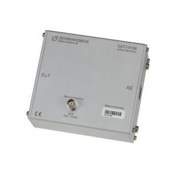
CAT3 8158, ISN for unshielded Cat 3 lines, Acc CISPR 32
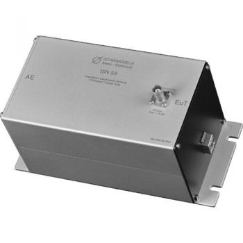
ISN S8, ISN for Shielded Telecom lines, Acc CISPR 32 - Discontinued
ISN S1, ISN for Coax Acc CISPR 32 - Discontinued
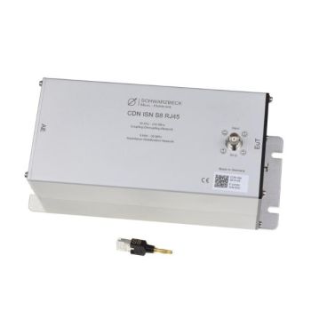
CDN ISN S8 RJ45, CDN/ISN for Shielded Telecom lines, Acc IEC 6100-4-6/CISPR 32
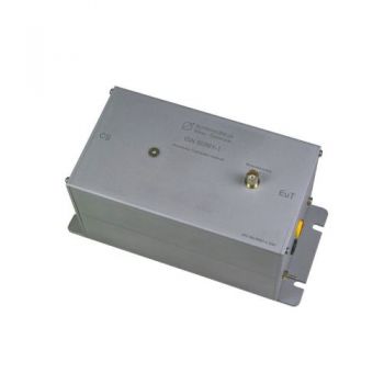
ISN 50561-1, ISN for PLC measurement, acc. EN 50561-1
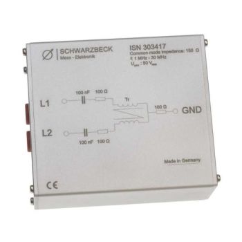
ISN 303417, ISN for 150 Ohm Common Mode Measurements
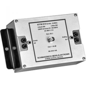
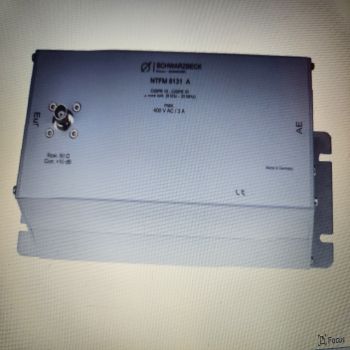
NTFM 8131, ISN for 2 unshielded Unsymetrical lines, Acc CISPR 32
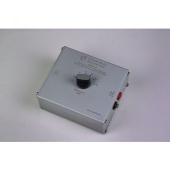
SYMAT 40, Symmetrical Step Attenuator, 100 Ohms acc. EN 50561-1
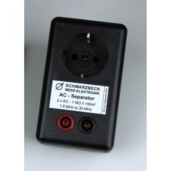
AC Separator, acc. EN 50561-1
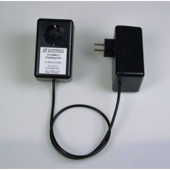
CU 50561-1, Coupling Unit , acc. EN 50561-1
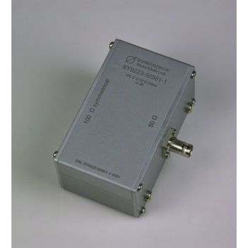
SY 9223-50561-1, Symmetrical Transformer, 50 to 100 Ohms acc. EN 50561-1
SPLIT 100, 2 way splitter, 100 Ohms acc. EN 50561-1
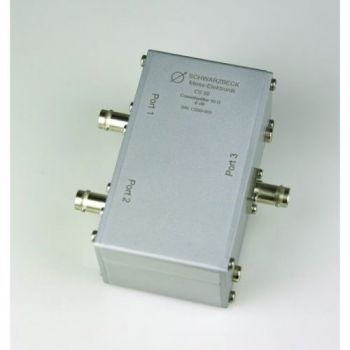
CS-50, 2 way splitter, 50 Ohms acc. EN 50561-1
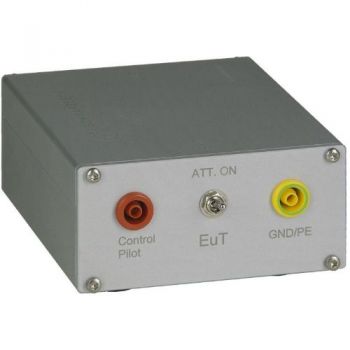
PILOT ISN, 150 kHz - 30 MHz, 1.4A, PLC
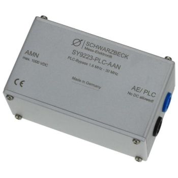
SY 9223-PLC-AAN, PLC bypass

