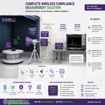
Band-Edge Emissions Testing: How the Right Preamplifier Can Reduce Test Time and Improve Measurement Confidence
Band-Edge Emissions Testing: How the Right Preamplifier Can Reduce Test Time and Improve Measurement Confidence

Introduction
Wireless products continue to expand into more crowded RF environments. Devices using Bluetooth, Wi-Fi, LTE, 5G NR, UWB, and other wireless technologies must demonstrate that they operate within their assigned frequency bands and do not create excessive interference outside those bands. These requirements are addressed through intentional radiator testing, including band-edge emissions measurements. FCC Part 15 regulations include requirements for controlling emissions outside authorized operating bands, with limits defined relative to the transmitter and applicable emission limits.
For EMC laboratories, band-edge testing presents a unique challenge. The measurement system must detect extremely low-level unwanted emissions while simultaneously handling the much stronger fundamental transmitter signal. A poorly selected preamplifier can become the limiting factor, creating distortion, requiring additional filters, increasing setup time, and potentially producing inaccurate results.
The correct high-dynamic-range preamplifier can simplify the measurement process by reducing overload concerns, minimizing filter changes, and improving confidence in the final measurement data.
What Is Band-Edge Emissions Testing?
A wireless transmitter is designed to operate within a specific frequency allocation.
For example:
2.4 GHz Wi-Fi / Bluetooth

The transmitter energy should remain inside this allocated band.
However, real transmitters produce unwanted emissions caused by:
- Modulation
- Power amplifier nonlinearity
- Harmonics
- Clock frequencies
- Digital processing
- Filtering limitations
These unwanted signals may appear immediately outside the allowed operating range.
Example:

The purpose of band-edge testing is to verify that these emissions are sufficiently attenuated.
Why Band-Edge Measurements Are Difficult
A typical radiated emissions measurement might involve detecting signals close to the receiver noise floor.
A wireless band-edge measurement is different.
The system may need to measure:
Strong transmitter signal
Example:
+20 dBm equivalent signal level
while also measuring:
Weak band-edge emission
Example:
-50 dBm
The measurement system must handle:
70 dB of signal difference.
This creates a challenge for every component in the RF path:
- Antenna
- Cable
- Filters
- Preamplifier
- Spectrum analyzer
The Preamplifier Is Often the Limiting Component
A common EMC measurement approach is:

The purpose of the preamplifier is to:
- Reduce the effective system noise floor
- Improve receiver sensitivity
- Compensate for cable loss

Preamplifiers are extremely valuable for radiated emissions testing because they amplify weak signals before they are degraded by receiver noise and cable losses.
However, gain alone is not enough.
A preamplifier must also maintain linear operation when strong RF signals are present.
The Problem With Traditional High-Gain Preamplifiers
Many preamplifiers are optimized primarily for:
- Low noise figure
- High gain
- Improved sensitivity
These are important specifications, but they do not tell the entire story.
The missing specification is:
Output 1 dB Compression Point (P1dB)
P1dB defines the output power level where the amplifier begins to leave its linear operating range.
When a preamplifier compresses:
- Gain is reduced
- Harmonics may be generated
- Intermodulation products may appear
- Sidebands can be distorted
- False emissions may be created
The result:
The measurement system may report emissions that are not actually produced by the device under test.
Why Notch Filters Are Commonly Used
A traditional solution is adding a notch filter before the preamplifier.
Example:
Without Filter

With Notch Filter

The filter removes the strong transmitter frequency while allowing the measurement system to examine the weaker emissions near the band edge.
However, filters introduce additional challenges:
- Additional insertion loss
- Additional calibration data
- More cables and connectors
- More setup complexity
- Filter selection for each wireless technology
- Additional measurement uncertainty
For laboratories performing many wireless tests, constantly changing filters can significantly increase test time.
The Advantage of a High-Dynamic-Range Preamplifier
A high-performance EMC preamplifier changes the measurement approach.
Instead of immediately filtering the transmitter, the system can often maintain linear operation without additional filtering.
The ideal measurement chain becomes:

Benefits:
- Faster measurements
- Fewer setup changes
- Reduced filter dependency
- Better signal integrity
- Improved repeatability
EMC118A45SE: Designed for Modern Wireless EMC Testing
The EMC118A45SE 1–18 GHz preamplifier was developed specifically for demanding EMC measurement applications where sensitivity and dynamic range are both important.
Key features:
1. Wide Frequency Coverage
One preamplifier covers:
- Bluetooth
- 2.4 GHz Wi-Fi
- 5 GHz Wi-Fi
- Wi-Fi 6E
- LTE
- 5G NR
- Other intentional radiator applications
Frequency range:
1 GHz to 18 GHz
This eliminates the need for multiple narrow-band amplifiers in many laboratories.
2. High Dynamic Range
The major advantage is not simply gain.
The EMC118A45SE provides:
- High gain
- High output compression capability
- Improved tolerance to strong RF signals
This is especially important for:
- Band-edge measurements
- Radiated spurious emissions
- Wireless certification testing
3. Reduced Dependence on Notch Filters
With a conventional lower-linearity amplifier, filters may be required to protect the input stage.
With a higher dynamic range amplifier:
- Some measurements can be performed without filters
- Fewer filter changes are required
- The RF path remains simpler
4. Better Preservation of the Actual Spectrum
A linear measurement system should reproduce the transmitter spectrum accurately.
A compressed amplifier can create:
- False harmonics
- Artificial spurs
- Distorted sidebands
Maintaining amplifier linearity helps ensure the measurement represents the actual EUT performance.
|
Frequency Range |
Wireless Technology / Standard |
Signal Type / Modulation |
Typical Products Using the Band |
Band-Edge Testing Focus |
|
2300–2400 MHz |
LTE Band 40 / 5G NR n40 |
OFDMA downlink, SC-FDMA uplink, OFDM |
Cellular routers, private LTE systems, industrial wireless gateways |
Verify emissions below 2300 MHz and above 2400 MHz |
|
2400–2483.5 MHz |
Bluetooth Classic, Bluetooth Low Energy (BLE), IEEE 802.11b/g/n Wi-Fi, Zigbee, Thread |
FHSS, GFSK, DSSS, OFDM, O-QPSK |
Headsets, wearables, IoT sensors, laptops, routers, smart home devices, automotive infotainment |
Lower edge near 2400 MHz and upper edge near 2483.5 MHz; very common FCC Part 15 testing |
|
2480–2500 MHz |
Bluetooth upper channels / ISM adjacent band |
GFSK, FHSS |
Bluetooth devices, IoT products, wireless accessories |
Upper band-edge emissions and adjacent restricted band measurements |
|
2496–2690 MHz |
5G NR n41 / LTE Band 41 |
OFDM TDD, OFDMA |
5G routers, private networks, cellular hotspots, industrial equipment |
High-power transmitters require high dynamic range measurement |
|
2500–2690 MHz |
LTE Band 7 / LTE Band 41 / Broadband Wireless |
OFDM, SC-FDMA |
Cellular equipment, wireless broadband devices |
Adjacent-band leakage and spurious emissions |
|
3300–3800 MHz |
5G NR n78 |
OFDM TDD |
Smartphones, fixed wireless access, private 5G networks |
Strong wideband carriers near band limits |
|
3300–4200 MHz |
5G NR n77 |
OFDM TDD |
Enterprise 5G, industrial automation, CBRS-related equipment, private cellular networks |
Wide occupied bandwidth requires accurate edge measurements |
|
4400–5000 MHz |
5G NR n79 |
OFDM TDD |
Industrial 5G, private networks, regional cellular systems |
Band-edge leakage into adjacent services |
|
5150–5250 MHz |
Wi-Fi UNII-1 (802.11a/n/ac/ax/be) |
OFDM, OFDMA |
Routers, laptops, enterprise access points |
Lower edge at 5150 MHz |
|
5250–5350 MHz |
Wi-Fi UNII-2A / DFS |
OFDM, OFDMA |
Enterprise Wi-Fi, access points, routers |
DFS channels and restricted-band emissions |
|
5470–5725 MHz |
Wi-Fi UNII-2C / DFS |
OFDM, OFDMA |
Enterprise WLAN, outdoor wireless systems |
Adjacent channel and DFS compliance testing |
|
5725–5850 MHz |
Wi-Fi UNII-3 |
OFDM, OFDMA |
Routers, wireless bridges, outdoor access points |
Upper edge and restricted-band testing |
|
5850–5925 MHz |
DSRC / ITS-G5 / C-V2X |
OFDM |
Connected vehicles, roadside units, automotive communication modules |
Automotive wireless compliance and adjacent-channel emissions |
|
5925–6425 MHz |
Wi-Fi 6E / Wi-Fi 7 |
OFDMA, Multi-Link Operation |
New-generation routers, laptops, enterprise APs |
New 6 GHz band-edge requirements |
|
6425–7125 MHz |
Wi-Fi 6E / Wi-Fi 7 |
OFDMA, 320 MHz channels, Multi-Link Operation |
High-performance routers, gaming devices, enterprise wireless |
Wideband edge measurements and high dynamic range testing |
|
5925–7125 MHz |
6 GHz Unlicensed Wireless |
OFDM/OFDMA |
Wi-Fi 6E/7 devices, industrial wireless systems |
Large bandwidth requires flexible filtering and measurement capability |
|
7125–8500 MHz |
Emerging Wi-Fi / Broadband Wireless / Defense Systems |
OFDM and proprietary digital modulation |
Future wireless systems, aerospace, defense communications |
Wideband spurious and band-edge measurements |
|
10 GHz Region |
Industrial radar / sensing systems |
FMCW radar, pulsed radar |
Industrial sensors, security systems, measurement equipment |
Transmitter leakage and harmonic emissions |
|
12–18 GHz |
Satellite communications, radar, microwave links |
QPSK, QAM, OFDM, pulsed modulation |
SATCOM terminals, aerospace systems, microwave equipment |
Wideband spurious emissions and harmonic testing |
The Hidden Cost of the Wrong Preamplifier
A lower-cost preamplifier may appear attractive initially.
However, the laboratory may spend more time:
- Troubleshooting unexplained emissions
- Adding notch filters
- Repeating measurements
- Changing RF configurations
- Validating questionable results
The real cost is not the amplifier purchase price.
The real cost is:
operator time, test delays, and measurement uncertainty.
Selecting the Right Preamplifier for Band-Edge Testing
When evaluating a preamplifier, consider:
|
Specification |
Why It Matters |
|
Frequency range |
Covers current and future wireless standards |
|
Gain |
Improves sensitivity |
|
Noise figure |
Determines receiver sensitivity improvement |
|
P1dB compression |
Determines overload capability |
|
Linearity |
Prevents false emissions |
|
Mounting location |
Minimizes cable loss |
|
Calibration compatibility |
Improves measurement confidence |
Conclusion
Modern EMC laboratories are increasingly performing measurements on products that intentionally transmit RF energy. These measurements require more than simply lowering the noise floor.
The best measurement system must:
- Detect weak emissions
- Handle strong transmitters
- Maintain linear operation
- Minimize setup changes
A high-dynamic-range preamplifier such as the EMC118A45SE allows EMC laboratories to perform challenging band-edge measurements faster and with greater confidence.
The correct preamplifier does not just improve sensitivity.
It improves the entire measurement process.