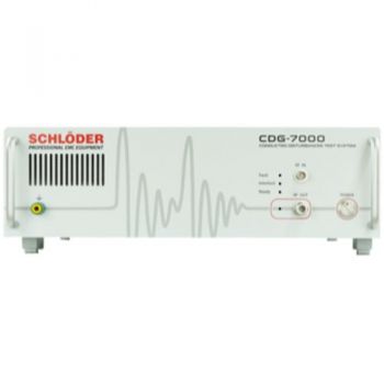
CDG 7000-E Conducted Immunity Generator, (4)9 kHz - 1 GHz , No internal Amplifier
The CDG 7000-E is a new test generator for all standards on immunity to conducted disturbances induced by high-frequency fields - including BCI tests (ISO 11452-4). One of the very few combined IEC 61000-4-6 test systems that contain the RF signal generator, a 3-channel RF voltmeter, and a directional coupler at a very affordable price. Use an external Amplifier you already have or one that matches your application.
- The compact device comprises an RF signal generator, a 3-channel RF voltmeter, and a directional coupler.
- Frequency range of the generator/power meter (4 kHz): 9 kHz – 1200 MHz
- The frequency range of the directional coupler: 10 kHz – 1000 MHz, 200 W
- Depending on ext. amplifier: IEC/EN 61000-4-6, IEC 60601-1-2 Ed. 4.1, IEC 61000-4-39, MIL 461 CS 114, ISO 11452-4, ...
PARTNER:
MARKETS:
CATEGORIES:
TEST STANDARDS:
Select Options/Sizes:

Software HELIA 7
Data Sheet
SPECIFICATIONS
CDG 7000-E Conducted-Immunity Generator
9 kHz – 1 GHz signal source | Drop-in amplifier flexibility | Standards-ready
Stop juggling separate RF sources, meters, and couplers.
CDG 7000-E folds them into one 19-inch chassis—then lets you bolt on the external power amplifier that best fits your test level or budget.
Why labs choose CDG 7000-E
| Integrated, future-proof core — built-in RF generator, 3-ch. power meter & directional coupler slash rack space. | |
|---|---|
| Plug-and-play external amps — pair any broadband or band-specific PA for IEC 61000-4-6, BCI, or MIL CS114 levels up to 200 W (optional 500 W coupler). | |
| 1 GHz bandwidth — covers traditional 150 kHz–230 MHz immunity plus medical IEC 60601-1-2 Ed 4.1 385 MHz/710 MHz & RFID, and emerging 900 MHz BCI needs. | |
| Helia 7 software included — point-and-click test templates, automatic reports, EUT monitoring, SCPI scripting, and optional BCI license for ISO 11452-4. | |
| SCPI + LAN/USB/GPIB — drops straight into automated benches and ATE racks. | |
| 3-year warranty & U.S. calibration/service from Absolute EMC—your productivity stays on schedule. |
Standards & test levels (generator + ext. PA)
-
IEC/EN 61000-4-6 (CE Mark, industrial, IT, residential)
-
IEC 60601-1-2 Ed 4.1 & IEC 61000-4-39 (medical close-proximity)
-
MIL-STD-461 CS114 (defense & avionics)
-
ISO 11452-4 (BCI) — with Helia 7-BCI option
-
IEC 61326-3-2 / NAMUR for process-control equipment
- RTCA DO160 BCI testing - Avionics
Technical snapshot
| Parameter | CDG 7000-E |
|---|---|
| Signal-generator range | 9 kHz – 1.2 GHz (usable from 4 kHz) |
| Directional coupler | 10 kHz – 1 GHz, 200 W (500 W option) |
| RF voltmeter channels | Test level + forward/reverse power, –40 to +30 dBm |
| Output level resolution | 0.1 dB (generator) |
| Path switching | 700 W internal relay matrix |
| Interfaces | USB 2.0, LAN 100 Mb/s, GPIB (opt.) |
| Dimensions / weight | 450 × 135 × 504 mm, ≈ 11 kg, 19″ 3 U |
| AC input | 100–240 VAC, 50/60 Hz, universal |
What’s in the box
-
CDG 7000-E mainframe
-
Helia 7 Basic software + USB licence key
-
Calibration certificate & user manual (USB stick)
-
RF & control harness: 4 × precision cables, 50 Ω loads, SMA/BNC adaptors
-
V-Lock mains cable & ground strap
-
Digital I/O connector blocks
-
3-year factory warranty
Typical configurations
| Application | Ext. Amplifier suggestion | Achievable level* |
|---|---|---|
| IEC 61000-4-6 (10 V) | 30 W broadband PA | 10 V EMF |
| ISO 11452-4 (60 dBμA) | 100 W 10 kHz–400 MHz PA | 100 mA clamp |
| MIL-STD-461 CS114 Lvl 5 | 200 W 10 kHz–200 MHz PA + 500 W coupler | 200 mA clamp |
*Levels assume conservative 6 dB AM; contact us for detailed budget.
Add-on accessories
-
CDNs & EM-clamps for power, signal, telecom lines
-
BCI calibration kits & current clamps
-
Near-field probes for root-cause trace
-
Pre-amps & attenuators for MIL CS114 high-severity testing
Absolute EMC stocks the full Schlöder accessory line and can ship within 24 hrs for most items.
Why buy from Absolute EMC?
-
Hands-on EMC labs – our Virginia facility runs the same gear we sell.
-
Turnkey approach – system integration, training, and annual calibration in one PO.
-
Local inventory & loaners – stay productive if your unit ever needs service.
-
Application engineering – decades of IEC, ISO & MIL immunity expertise on call.
Need higher field levels or full turnkey immunity benches?
Ask us about bundling the CDG 7000-E with our broadband RF amplifiers, precision CDNs, and automated EUT monitoring packages.
Absolute EMC – accelerating EMC compliance with expert support and best-in-class test systems.
OTHER PRODUCTS IN THE SAME CATEGORY:


400 - 6112, 2-Ch, 250kS/s, AnyWave Control Unit
400 - 6361, 2-Ch, 2.8MS/s, AnyWave Control Unit
CDG 7000-75-10 Magnetic Immunity, 10 kHz - 400MHz, IEC 61000-4-39
CDG 7000-E Conducted Immunity Generator, (4)9 kHz - 1 GHz , No internal Amplifier

AN-ABCD-300, 300 Amp Artificial Network, EV HV Testing
CABAI20050, 200W, 50 A, 2:1, Audio Isolation Transformer
CDG 7000 Conducted Immunity, (4)10 kHz - 400MHz
CDG 7000-200 Conducted Immunity, 4 kHz - 400MHz, 200Watts
MAG 1000, 120A/m CW, 1100Am Short Duration, Power Frequency Magnetic Field
240-1C, 0-240V, 27-2000+kW, DC Power Supply, Sink/Source
320-1C, 0-320V, 36-2000+kW, DC Power Supply, Sink/Source
1500-1C, 0-1500V, 27-2000+kW, DC Power Supply, Sink/Source
60-1C, 0-60V, 9-2000+kW, DC Power Supply, Sink/Source
500-1C, 0-500V, 9-2000+kW, DC Power Supply, Sink/Source
1000-1C, 0-1000V, 18-2000+kW, DC Power Supply, Sink/Source
80-1C, 0-80V, 9-2000+kW, DC Power Supply, Sink/Source
160-1C, 0-160V, 18-2000+kW, DC Power Supply, Sink/Source
2000-1C, 0-2000V, 36-2000+kW, DC Power Supply, Sink/Source
3000-1C, 0-3000V, 54-2000+kW, DC Power Supply, Sink/Source

