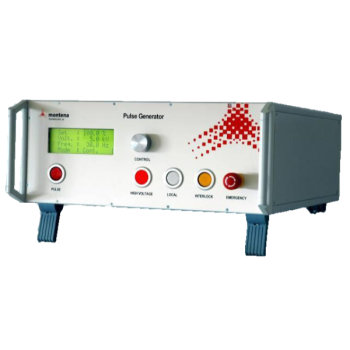
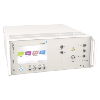
IPG 612T: 6kV RING-WAVE GENERATOR
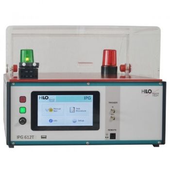
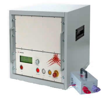
IPG 612T RING-WAVE GENERATOR is a High-voltage pulse generator producing Ring Wave 0.5 µs / 100 kHz acc. to IEC 61000-4-12. The output peak voltage can be preset continuously from 0.2 - 6 kV. Rise time 0.5µs to the first peak, ringing frequency 100 kHz. The picture is shown with PA 503 Option.
PARTNER:
MARKETS:
CATEGORIES:
TEST STANDARDS:

Data Sheet
SPECIFICATIONS
IPG 612T
RING-WAVE GENERATOR
Output voltage 0.2 – 6 kV
Frequency 100 kHz Rise time 0.5µs
|
According to |
|
|
IEC 61000-4-12 |
Ring wave test |
|
IEC 1008-1 |
Ring wave test of RCCB´s |
High-voltage pulse generator producing Ring Wave 0.5 µs / 100 kHz acc. to IEC 61000-4-12. The output peak voltage can be preset continuously from 0.2 - 6 kV. Rise time 0.5µs to the first peak, ringing frequency 100 kHz.
A built-in voltage divider allows monitoring of the output voltage waveform.
The generator comprises an electronically regulated high-voltage power supply, an energy storage capacitor, a high-voltage/high-current switch, a pulse forming network and a control- and monitoring unit.
Moreover, the generator includes a Coupling-/Decoupling Network (CDN) for single-phase power supply lines. External coupling-/decoupling networks for 3-phase power supply lines are controlled by a built-in optical interface.
High-voltage pulses are generated synchronous with the mains power supply, phase shifting is digitally selectable.
The generator excels by its compact design, simple handling and precise reproducibility of test impulses. It features a microprocessor controlled user interface and a 7” touch screen unit for ease of use. The microprocessor allows the user to execute either standard test routines or a “user-defined” test sequence. A standard USB port provides the ability to print a summary of the test parameters to a USB stick.
The software program IPG-REMOTE allows full remote control of the test generator via Ethernet light guide as well as documentation and evaluation of test results, accordingly to the IEC 17025. To record definite impulses, it is equipped with an Impulse Recording Function (IRF) Moreover all generator functions may be computer controlled via the isolated optical interface.
|
Options |
IPG 612T |
|
|
|
|
Software IPG-REMOTE, for remote control |
|
|
With Impulse Recording Function (IRF) |
|
|
( XP, WIN7, WIN10 ) incl. 5m long light guide and PC Ethernet interface |
|
|
|
|
|
Modification for testing residual current operated circuit breakers (RCCB) |
|
|
Modification for testing residual current operated circuit breakers (RCCB) acc. to IEC 1008-1 |
|
|
|
|
|
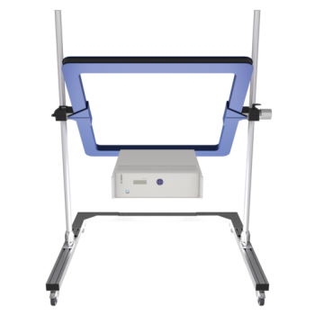
PROTECTIVE COVER ON THE EQUIPMENT TOP |
|
|
With safety interlock switch, connected to the safety interlock loop, red and green warning lamps installed acc. VDE 0104. |
See figure |
|
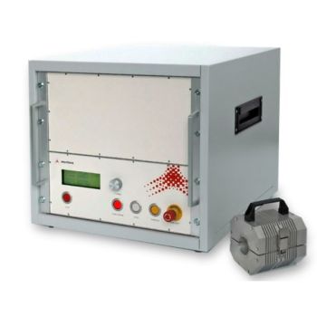
Typ PA 503, Dimensions W * H * D |
400 * 140 * 300 mm³ |
|
Typ PA 505, Dimensions W * H * D |
400 * 250 * 400 mm³ |
|
Accessories |
IPG 612T |
|
|
|
|
Coupling-/decoupling networks |
|
|
For 3-phase interference test acc. to IEC 61000-4-12 |
CDN 5416, CDN 2410 |
|
TECHNICAL SPECIFICATION |
IPG 612T |
|
|
|
|
Mainframe |
|
|
Microprocessor controlled touch panel |
7”, capacitive |
|
Optical Ethernet Interface for remote control of the generator |
Optional |
|
Interface for saving reports |
USB |
|
External Trigger input/ output |
Switch/ 10V |
|
Connector for external safety interlock loop |
24 V= |
|
External red and green warning lamps |
230V / 60 W |
|
Mains power |
90V – 264V / 50/60 Hz |
|
Dimensions of desktop case W * H * D |
450*180*500 mm3 |
|
Weight |
18kg |
|
|
|
|
Generator section |
|
|
Impulse output voltage, adjustable |
0.2 - 6.0 kV ± 10 % |
|
Output wave form acc. to IEC 61000-4-12 |
0.5 µs /100 kHz |
|
Oscillation frequency |
100 kHz ± 10% |
|
Voltage rise time to the first peak (open) |
0.5 µs ± 30% |
|
Current rise time to the first peak (short) |
<= 1 µs |
|
Decaying voltage |
0,4 < Ratio of Pk2 to Pk1 < 1,1 0,4 < Ratio of Pk3 to Pk2 < 0,8 0,4 < Ratio of Pk4 to Pk3 < 0,8 |
|
Polarity of output voltage |
+/-, selectable |
|
Maximum stored energy |
10 Ws |
|
Repetition rate, max. |
60 transients per minute |
|
|
|
|
High-voltage output HV-OUT, impedance selectable: |
|
|
PFN 1: Series resistor / max. short circuit output current 5kV |
10 + 2 W / 416A |
|
PFN 2: Series resistor / max. short circuit output current 5kV |
10 + 20 W / 166A |
|
COM: male connector, potential free |
250 V/50 Hz, 1000 Vpeak |
|
|
|
|
Impulse voltage divider integrated |
ratio = 1000:1 ± 5% |
|
Triggering : a) manual |
key |
|
b) ext. trigger input |
switch |
|
c) internal, automatic |
test procedure |
|
Mains synchronous trig.: Phase shifting, digitally selectable |
0 - 360 ° ±5° |
|
|
|
|
Coupling-/decoupling network for power supply lines, built-in |
L1, N, PE |
|
rated voltage, rated current |
250 V, 16 A » / 10 A = |
|
Coupling mode, selectable: “Line to Line” and “Line to Ground” |
Cc = 10 µF |
Option 2: Ring Wave Test of RCCB´s acc. to IEC 1008-1
The Ring-Wave Generator IPG 612T can be used for testing Residual Current operated Circuit Breakers (RCCB´s) according to IEC 1008.
During this test, each current path of the RCCB is loaded with a ring wave current. Up to peak current values of 250 A the RCCB may not be triggered.
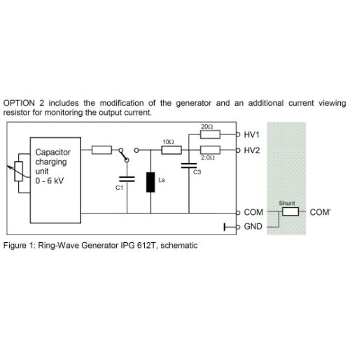
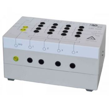
OPTION 2 includes the modification of the generator and an additional current viewing resistor for monitoring the output current.
See fig1
The Ring-Wave Generator IPG 612T can be modified for testing Residual Current operated Circuit Breakers (RCCB´s) according to IEC 1008 as follows:
1. The terminal COM is short-circuited to terminal GND.
2. In order to monitor the output current a current viewing resistor Rm = 2 mW is connected in series to the COM-terminal.
Modifications 1 and 2 are accomplished by connecting the specially designed SHUNT to the output terminals.
Protective earth terminals of the RCCB must be connected to the terminal COM’. Additional accessories see Options
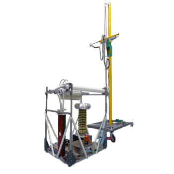
Option 3: Ring Wave Test of RCCB´s acc. to IEC 1008-1including safety test cover PA 503
The Ring-Wave Generator IPG 612T can be used for testing Residual Current operated Circuit Breakers (RCCB´s) according to IEC 1008. During this test, each current path of the RCCB is loaded with a ring wave current. Up to peak current values of 250 A, the RCCB may not be triggered.
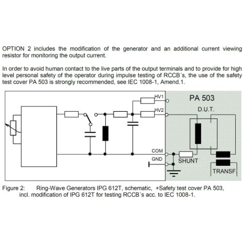
OPTION 3 includes the modification of the generator and an additional current viewing resistor for monitoring the output current.
See Fig2
1. The COM terminal is connected to GND.
2. In order to monitor the output current a current viewing resistor Rm = 2 mW is connected between the test object and the COM/GND-terminal.
3. The high-voltage outputs HV-1 and HV-2 are connected to the safety test cover.
4. The safety test cover includes an isolating transformer with EMI-filter to supply the test object
5. The limit switch of the safety test cover is connected to the safety interlock loop of the generator. Upon opening the safety test cover, the generator is shut down.
OTHER PRODUCTS IN THE SAME CATEGORY:
IPG 612T: 6kV RING-WAVE GENERATOR
CDN 5404, 4 line, Ringwave, Coupling Decoupling Network
RW-CE7: 7kV Ringwave, 5µs 100 kHz
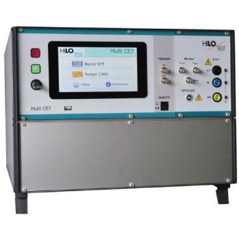
Multi-CE7 5KV EFT, 7kV SURGE, Ringwave, 10/700, DIPS/DROPS/VARIATIONS
PG-CS115 - CS115 Test Generator, 1kV into 50 Ohms
POG-CS116-CS115 Test Generator, Dampened Wave and Switch Transients
PG1275F - MIL-STD-1275F Surge/Spike Test Generator
POG-CS116 - Test Generator, Dampened Wave

AN-ABCD-60, 60 Amp Artificial Network, EV HV Testing
PGESD 300K DP - Helicopter 300kV ESD Test System
PSURGE 30.2 Modular 30 kV / 30 kA Surge Test System
PEFT 8010 EFT/Burst Test System up to 7.3 kV
MAG 1000, 120A/m CW, 1100Am Short Duration, Power Frequency Magnetic Field
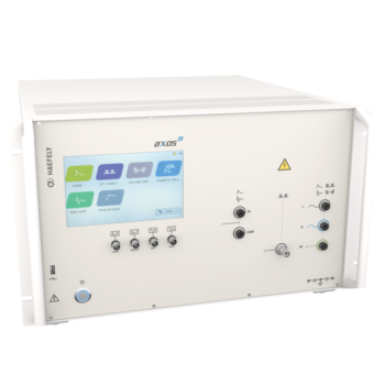
Axos 8 - Compact 7kV Surge, Telecom, Ring Wave, 5kV EFT, Dips/Drops
Axos 5 - Compact 5kV EFT, Surge, Dips/Drops
ONYX 30, 30kV ESD Simulator

AN-ABCD-300, 300 Amp Artificial Network, EV HV Testing

400 - 6361, 2-Ch, 2.8MS/s, AnyWave Control Unit
400 - 6112, 2-Ch, 250kS/s, AnyWave Control Unit

