Multi-CE7 5KV EFT, 7kV SURGE, Ringwave, 10/700, DIPS/DROPS/VARIATIONS
The Multi-CE7 is a compact EMC test unit designed for testing electromagnetic immunity against pulsed and conducted interference. Demonstrating such immunity is generally a requirement for compliance with the European EMC directive, a necessary step leading to the CE mark. In its basic configuration, the Multi-CE5 includes an Electrical Fast Transient Generator (EFTG), a Combination Wave Generator (CWG), Option: RingWave Generator (RWG), Option: 10/70 Telecom Generator (TWG), Option: Dip/Drops/Interruptions, and a Coupling-/Decoupling Network (CDN) for single-phase power supply lines.
PARTNER:
MARKETS:
CATEGORIES:
TEST STANDARDS:

Data Sheet
SPECIFICATIONS
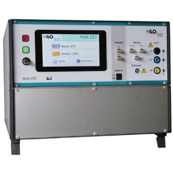
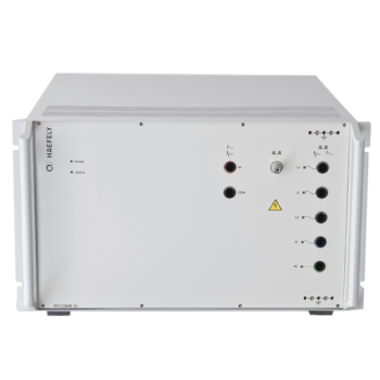
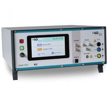
Multi CE7
Compact EMC-tester
IEC 61000-4-04, IEC 61000-4-05, IEC 61000-4-08, IEC 61000-4-09, IEC 61000-4-11, IEC 61000-4-12, IEC 60060-2, IEC 61000-4-29
|
According to |
|
|
IEC 61000-4-4 : 2012 |
BURST 5kV |
|
IEC 61000-4-5 : 2014 |
SURGE 7kV, 3.5kA |
|
IEC 61000-4-8 : 2010 |
Magnetic field 50/60 Hz |
|
IEC 61000-4-9 : 2001 |
Magnetic field 8/20 µs |
|
IEC 61000-4-11 / 29 : 2004 |
Voltage dips/variation |
|
IEC 61000-4-12 |
Ringwave Generator 7kV |
|
ITU, FCC part 68 and IEC 61000-4-5 |
Telecom Surge 7kV |
The Multi-CE7 is a compact EMC test unit designed for testing electromagnetic immunity against pulsed and conducted interference. Demonstrating such immunity is generally a requirement for compliance with the European EMC directive, a necessary step leading to the CE mark.
In its basic configuration, the Multi-CE7 includes an Electrical Fast Transient Generator (EFTG-CE5), a Combination Wave Generator (CWG-CE7) and a Coupling-/Decoupling Network (CDN) for single-phase power supply lines.
The Electrical Fast Transient Generator fully compliant to IEC 61000-4-4, delivers fast transient pulses with waveform 5/50 ns and a maximum burst frequency of 1 MHz. It is used for immunity testing of electronic systems and devices. The four standard IEC 61000-4-4 test levels may be easily selected by push button or all parameters may be adjusted individually.
The Combination Wave Generator fully compliant to IEC 61000-4-5 and IEEE 587 delivers a standard impulse voltage with waveform 1.2/50 µs and a standard impulse current with waveform 8/20 µs. It is a combined impulse-current-/impulse-voltage generator for high- impedance loads RL > 100W and may be used for surge testing of components and devices, as well as for galvanic coupling of surges to cable shields, shielded enclosures and cabinets.
The built-in capacitive Coupling-/Decoupling Network allows superimposition of the combination wave generator output to the mains voltage of the device under test.
The simulation of voltage dips and voltage variations acc. to IEC 61000-4-11 can be included as an option. Additional accessories allow the testing of immunity against both pulsed and power frequency magnetic fields according to IEC 61000-4-8 and IEC 61000-4-9.
Optionally the Multi-CE7 can include a triggerable power supply switch which allows the simulation of the voltage dips as specified in the standard IEC 61000-4-11. The variation of the power supply voltage is controlled by the use of an external motor driven variac. The control of the external power source is included in the mainframe.
Another option is the high-voltage pulse generator producing Ring Wave 0.5 µs / 100 kHz acc. to IEC 61000-4-12.The output peak voltage can be present continuously from 0.25 - 7 kV. Rise time 0.5µs to the first peak, ringing frequency 100 kHz.
As well as the high-voltage pulse generator creating standard impulse voltages with waveform 10/700 µs. It is designed for dielectric testing of components and systems as well as testing of the electromagnetic compatibility of electronic systems and devices acc. to CCITT- K17/K20/K22, ITU-T/K44, IEC 61000-4-5 etc.
An Induction Coil in conjunction with the Combination Wave Generator output is used to simulate pulsed magnetic fields according to IEC 61000-4-9. Combined with the external power source, the Induction Coil can be used to simulate power frequency magnetic fields according to IEC 61000-4-8.
Additional Coupling-/Decoupling Networks covering three-phase power supply lines, DC supply lines and signal lines are also available, as well as a Capacitive Coupling Clamp for coupling to shielded interconnection lines.
The Multi-CE7 excels by its compact design, simple handling and precise reproducibility of test impulses. It features a microprocessor controlled user interface and a 7” touch screen unit for ease of use. The microprocessor allows the user to execute either standard test routines or a “user-defined” test sequence. A standard USB port provides the ability to print a summary of the test parameters as well as the results to a USB stick.
The software program CE-REMOTE allows full remote control of the test generator via Ethernet light guide as well as documentation and evaluation of test results, accordingly to the IEC 17025. To record definite impulses, it is equipped with an Impulse Recording Function (IRF).
Moreover all generator functions including the built-in Coupling-/Decoupling Network, maybe computer controlled via the isolated optical interface.
System configuration
The Multi-CE7 and its sub-units are available in different configurations:
|
Variations |
Description |
|
Multi-CE7 1 |
including SURGE and BURST |
|
Multi-CE7 2 |
including SURGE, BURST, and POWER FAIL SWITCH |
|
EFTG-CE5 |
Stand-alone BURST generator |
|
CWG-CE7 |
Stand-alone SURGE generator |
|
PFS-CE-16 |
Stand-alone POWER FAIL SIMULATOR Including a power fail switch and a variable power source |
Typical configurations:
Multi-CE7 1 + CDN 7416
for 3-phase testing
Multi CE7 2 + VPS 250-16
for testing surge, burst, power fail, voltage dips and variation
It is possible to build all devices in a 19” rack cabinet.
|
Options |
Multi CE7 |
|
|
|
|
Software CE-REMOTE Test, for remote control |
|
|
With Impulse Recording Function (IRF) |
|
|
( XP, WIN7, WIN10 ) incl. 5 m fiber optic cable and PC Ethernet interface |
|
|
|
|
|
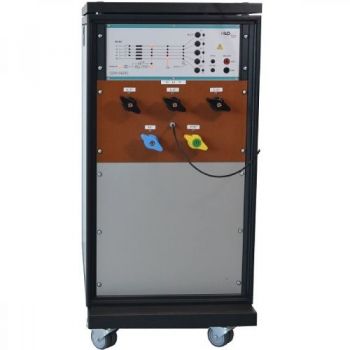
External power source VPS 250-16 |
|
|
Output voltage, adjustable |
0 - 250 V |
|
Rated current |
16 A |
|
Control via interface of Multi CE7 |
|
|
|
|
|
Induction Coil HI 200 acc. to IEC 61000-4-8/9: 2010/2001 |
|
|
Dimensions: W * H * D |
1000*1000*600 mm3 |
|
Coil factor |
1.5 / m |
|
|
|
|
EFTC2012 Coupling Clamp acc. to IEC 61000-4-4:2012 Ed 3.0 |
|
|
Dimensions: W * H * D |
140 * 180 *1100 mm³ |
|
Incl. Connection cable, Fischer Koax Connector |
1 m long |
|
Maximum cable diameter: |
ca. 42mm |
|
TECHNICAL SPECIFICATIONS |
Multi CE7 |
|
|
|
|
Mainframe |
|
|
Microprocessor controlled touch panel |
7”, capacitive |
|
Optical Ethernet Interface for remote control of the generator |
optional |
|
Interface for saving reports |
USB |
|
External trigger input/ output |
Switch/ 10 V |
|
Coupling-/decoupling network for power supply lines |
L1, N, PE (ISO, optional ANSI) |
|
Nominal voltage, nominal current |
250 V, 16 A » / 16 A = |
|
Coupling impedance (depending on the generator) |
33 nF / 18 µF / 9µF+10W |
|
Connector for external safety interlock loop |
24 V = |
|
External red and green warning lamps |
230 V, 60W |
|
Mains power |
90V - 264V, 50/60 Hz |
|
Dimensions of desktop case W * H * D |
450*330*500 mm3 |
|
Weight |
25 kg |
|
|
|
|
BURST acc. to IEC 61000-4-4: 2012 |
|
|
Pulse output voltage, adjustable |
0.2 - 5.0 KV ± 10 % |
|
Waveform |
5/50 ns |
|
Source impedance |
50 W |
|
Polarity, selectable |
pos/neg/alt |
|
Burst frequency, adjustable |
1.0 kHz - 1.0 MHz |
|
Burst duration, adjustable |
0,01 ms - 25 ms |
|
Burst period, adjustable |
10 ms - 1000 ms |
|
HV output for external coupling devices |
coaxial |
|
Monitor output for pulse output voltage |
ratio = 100:1 ± 5%, 50 W |
|
|
|
|
SURGE acc. to IEC 61000-4-5: 2014 |
|
|
Test voltage (open circuit condition) |
0.25 - 7.0 kV ± 10 % |
|
Waveform acc. to IEC 60060 |
1.2 / 50 µs ± 20 % |
|
Test current (short circuit condition) |
0.25 - 3.5 kA ± 10 % |
|
Waveform acc. to IEC 60060 |
8 / 20 µs ± 20% |
|
Polarity of output voltage/current, selectable |
pos/neg/alt |
|
Maximum stored energy |
250 Joule |
|
Charging time for max. charging voltage |
< 20 s |
|
HV output isolated from ground |
HV-OUT, 4mm |
|
Mains synchronous triggering, phase shifting, digitally selectable |
0 - 359°, step 1° |
|
Monitor output for pulse output voltage |
ratio = 1000 : 1 ± 5% |
|
Monitor output for pulse output current |
10 V º 5 kA ± 5% |
|
POWER FAIL (option) acc. to IEC 61000-4-11: 2004 |
||
|
Rated current / Inrush current, max. |
16 A / 500A |
|
|
Monitor output for mains voltage and mains current |
built-in |
|
|
Display of mains voltage, mains current and inrush current Interface for control of an external power source |
||
|
|
||
|
RINGWAVE (option) acc. to IEC 61000-4-12: 2004 |
||
|
Impulse output voltage, adjustable |
0.25 - 7.0 kV ± 10 % |
|
|
Output waveform acc. to IEC 61000-4-12 |
0.5 µs /100 kHz |
|
|
Oscillation frequency |
100 kHz ± 10% |
|
|
Voltage rise time to the first peak (open) |
0.5 µs ± 30% |
|
|
Current rise time to the first peak (short) |
<= 1 µs |
|
|
Decaying voltage |
0,4 < Ratio of Pk2 to Pk1 < 1,1 0,4 < Ratio of Pk3 to Pk2 < 0,8 0,4 < Ratio of Pk4 to Pk3 < 0,8 |
|
|
Polarity of output voltage |
pos / neg, selectable |
|
|
Maximum stored energy |
12 J |
|
|
Repetition rate, max. |
60 transients per minute |
|
|
|
||
|
High-voltage output HV-OUT, impedance selectable: |
||
|
PFN 1: Series resistor |
12 W (10+2 W) |
|
|
PFN 2: Series resistor |
30 W (10+20 W) |
|
|
Impulse voltage divider integrated |
ratio = 1000:1 ± 5% |
|
|
|
||
|
Mains synchronous trig.: Phase shifting, digitally selectable |
0 - 360 ° ±5° |
|
|
|
||
|
TSURGE (option) acc. to ITU, FCC part 68 and IEC 61000-4-5 |
||
|
Peak value of impulse output voltage, adjustable, 1 V steps |
0.25 - 7.0 kV ± 10 % |
|
|
Waveform of impulse output voltage, acc. to IEC 60600 |
||
|
Surge waveform, acc. IEC60600-1 |
10/700µs ±30/±20% |
|
|
Energy storage capacitor |
CS |
20 µF |
|
Max. stored energy |
WE |
490 J |
|
Discharging resistor |
RE |
50 W |
|
Damping Resistor |
RD |
15 W |
|
Load capacitance |
CB |
0.2 µF |
|
|
||
|
Resistor in series to the output RS Outputs: 1xdirect; 4x25W |
4 * 25 W RGes=RD+Rs = 40W |
|
|
Output polarity, selectable |
pos / neg /alt |
|
|
|
||
|
Repetition time, selectable |
20-1000 s |
|
|
Impulse voltage divider, built-in |
ratio= 1000:1 ± 2 % |
|
|
|
||
|
Current Sense: |
||
|
Threshold value, selectable |
1-2500 µAs |
|
|
Current sense working range |
0.25 kV - 7kV-max |
|
|
HV output, HV-OUT |
HV connectors |
|
|
Mains synchronous triggering, phase shifting, digitally selectable |
0 - 360 °, step 1° |
|
OTHER PRODUCTS IN THE SAME CATEGORY:
Axos 8 - Compact 7kV Surge, Telecom, Ring Wave, 5kV EFT, Dips/Drops
Axos 5 - Compact 5kV EFT, Surge, Dips/Drops
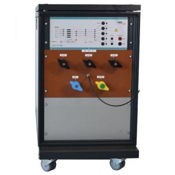
FP-COMB 32, Combined Automatic 3-Phase Coupling / Decoupling Network
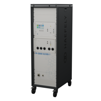
FP-COMB 63/690-1, Combined Automatic 3-Phase Coupling / Decoupling Network

ESD Test Table Kit
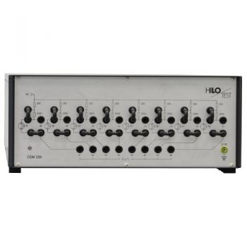
CDN 54125 / 74125 / 104125 / 124125, 3-Phase, 125 Amp, Surge and EFT/burst, Coupling Decoupling Netw
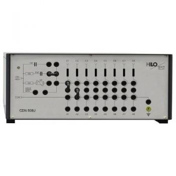
CDN 504U / CDN 508U, 4/8-Line, Surge and EFT/burst, Coupling Decoupling Network
CDN 504-sym / CDN 508-sym, Signal 4/8-Line, Surge and EFT/burst, Coupling Decoupling Network
CDN 54200 / 74200 / 104200 / 124200, 3-Phase, 200 Amp, Surge and EFT/burst, Coupling Decoupling Net.
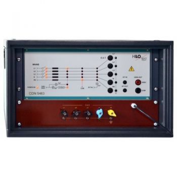
CDN 5463 / 7463 / 10463 / 12463, 3-Phase, 63 Amp, Surge and EFT/burst, Coupling Decoupling Network

CDN 5432 / 7432 / 10432 / 12432, 3-Phase, 32 Amp, Surge and EFT/burst, Coupling Decoupling Network
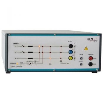
CDN 10216 & 12216, 2-line, 16 Amp, Surge and EFT/burst, Coupling Decoupling Network

CDN 5416 / 7416 / 10416 / 12416, 3-Phase, 16 Amp, Surge and EFT/burst, Coupling Decoupling Network
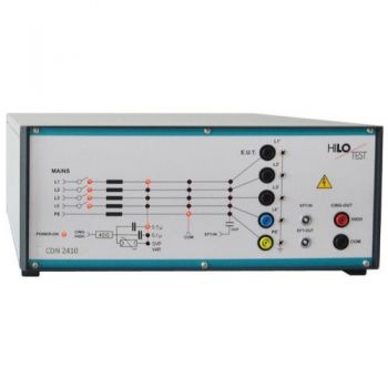
CDN 2402 & CDN 2410, Signal Line, Surge and EFT/burst, Coupling Decoupling Network
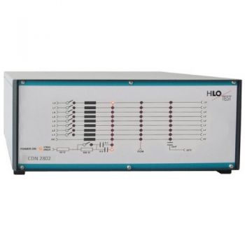
CDN 2802, Signal 8-Line, Surge and EFT/burst, Coupling Decoupling Network
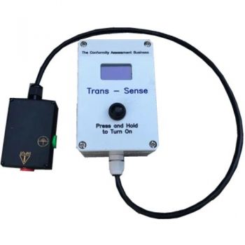
Trans-Sense Quick pre-check of IEC 61000-4-4 EFT

EFT 2012 EFT/Burst Capacitive Coupling Clamp
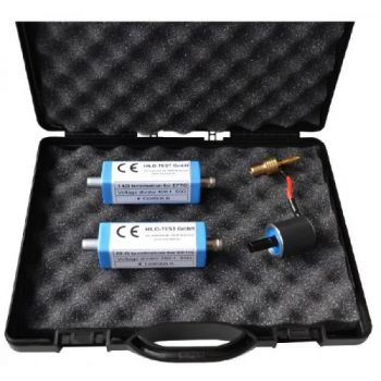
BCK 400 F Calibration kit for EFT/burst Generators
EFTG-CE5: 5kV, EFT 5/50ns, 1-1000 kHz

