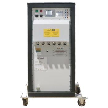
100-TS, 4-Quadrant Current Amplifiers 400 W - 54,000 W
- DC - 200 kHz bandwidth DC
- MHz (small signal -3 dB)
- Output voltage ±75 Vpk
- Rise / fall time 100 V/µs
- USB interface standard, LAN optional
- Analog control input 0 ... ±10 V for control of voltage and current
- Monitor outputs for measured voltage and current values (not all models)
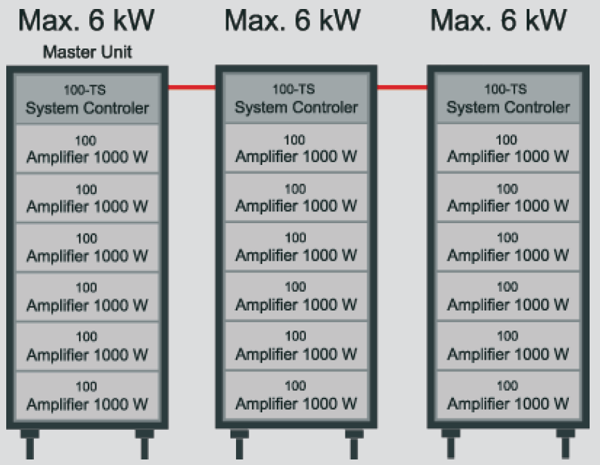
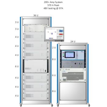
- Modularly extensible via master-slave mode
- Parallel and Series Connections for two or more units
PARTNER:
MARKETS:
- Automotive ,
- Avionics ,
- Information Technology ,
- Medical Electronics ,
- Military ,
- Power Generation ,
- RF ,
- Space ,
CATEGORIES:
TEST STANDARDS:
- FMC1278 ,
- GM W 3097 ,
- ISO 16750-2 ,
- ISO 7637-2 ,
- ISO 7637-4 ,
- ISO/IEC 18092 ,
- LV 124 ,
- LV 148 ,

Data Sheet
SPECIFICATIONS
Arbitrary 4-Quadrant Voltage Amplifiers100-TS Series 400 W - 54,000 W, DC - 200 kHz / 1 MHz
Special Features
Model 35N-TS Overview+35 V / -16 V
Model 110-70N-TS Overview+70 V / -16 V
Model 75N-TS Overview+75 V / -75 V
Selectable Operating Voltage Three selectable operating-voltage ranges allow adapting to applications for high voltage / low current or low voltage / high current. Especially when controlling extremely low impedance loads, the operating voltage range can be reduced to one-third of the maximum output voltage, which greatly reduces power dissipation.
General The 100-TS series are linear precision
They also work as sink-in applications to absorb power. This series is characterized by extremely high bandwidth at the highest power requirements, which is necessary for fast signals. Primarily, these amplifiers are characterized by their signal quality.
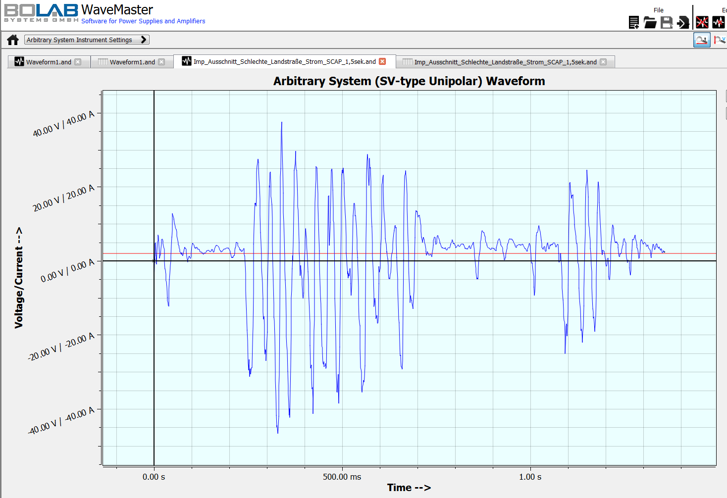
Arbitrary Functionality BOLAB´s arbitrary power amplifiers include a vast memory of 1 Million data points to store arbitrary waveforms in the instrument. No arbitrary waveform generator or other controlling instrument is needed, making these 4-quadrant amplifiers unique in the world market. The easy-to-use WaveMaster software, which is standard in scope of delivery, allows generating waveforms with a graphical user interface or via tabular input.
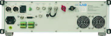
Monitor Outputs Located on the back of the instruments, there are monitor outputs for voltage and current with the respective measured values. Output values are 0 ... ±10 V for 0 ... ±Vrated respectively 0 ... ±IIrated. The current is measured with an internal shunt and accuracy of approx. 1 %. Optionally, a current sensor with 0.01 % accuracy can be integrated easily.
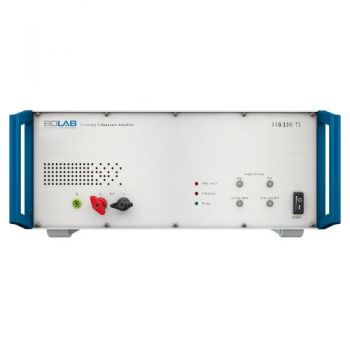
Output ON/OFF The output on/off switch at the front of the instruments allows the output to be activated or deactivated. When deactivated, the devices under test are completely galvanically separated.
Protective Functions Various protective functions avoid damage to the instrument and guarantee protection for the devices under test. Output voltage and current can be limited. An over-temperature shutdown is included. The unit’s internal power dissipation calculation and complete current monitoring ensure perfect short circuit and over-voltage protection. Also, for security reasons, an interlock shutdown can be triggered.
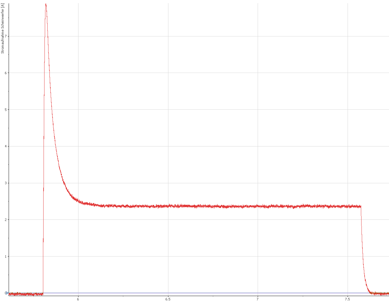
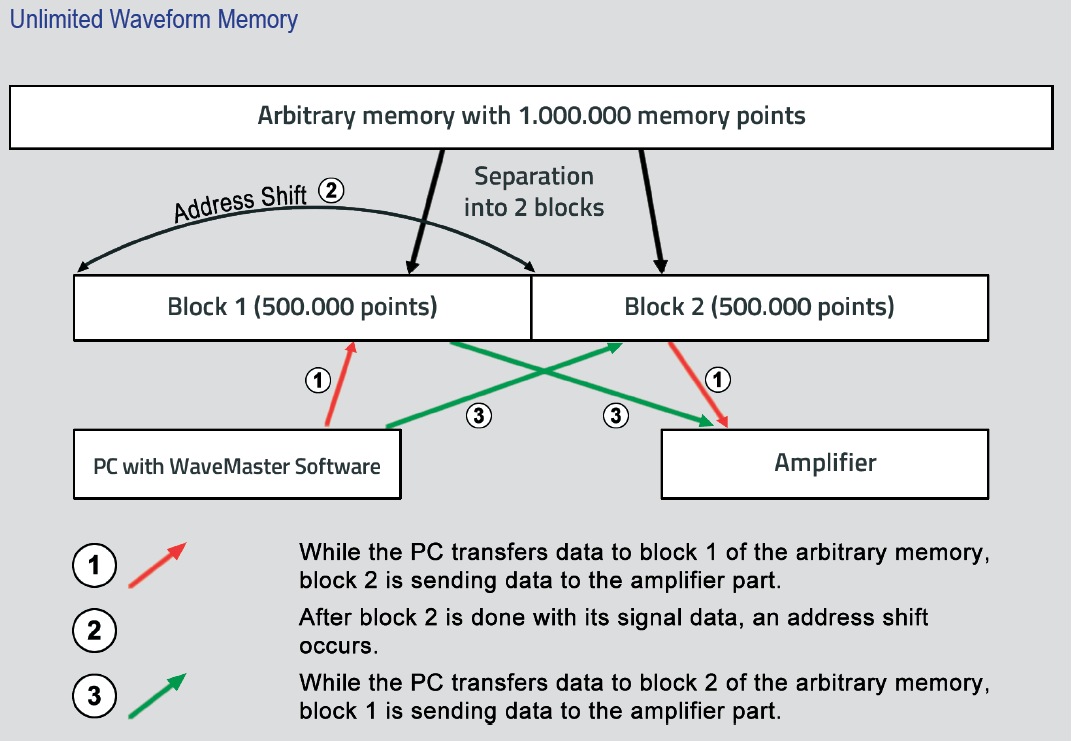
Unlimited Waveform Memory c::: This technology enables an endless, continuous data stream to the amplifier. c::: Unlike a function generator with its limited arbitrary memory, the size of the waveform is not limited. c::: A waveform with small spikes and interruptions of, for example, 100 µs and long constant levels in between can be easily simulated.
Voltage And Current Control Both voltage and current control of the comprehensive amplifiers is possible. This can be selected on the front panel of the instrument. Control input is 0 ... ±10 V for 0 ... ±Vrated respectively 0 ... ±IIrated. An optional compensation network for current control is necessary, which achieves the highest slew rates and signal quality for current signals.
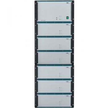
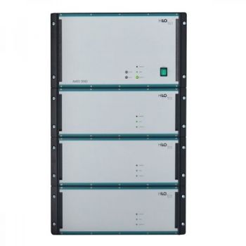
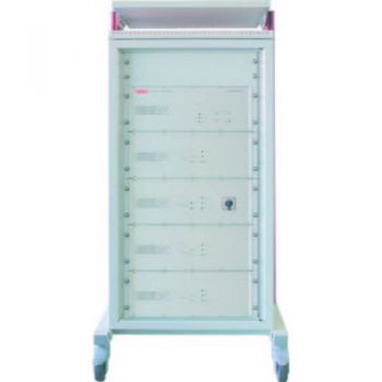
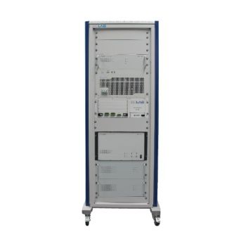
Modular Concept / Modularly Expandable
WaveMaster Software Waveform generation and 4-quadrant amplifier control
Special Features
Waveform Generation The powerful and easy-to-use WaveMaster software is unique in the world market. Without any knowledge of software development, constructing ordinary and complex waveforms is easy. A graphical waveform editor allows the generating of individual curves in a flash. Also, tabular input can produce all kinds of waveforms immediately. The simplicity of how fast data can be imported out of oscilloscopes is fantastic. Reading in ASCII data files is possible in the same way.
Digital Interface USB All functionalities of the 4-quadrant amplifiers are available in WaveMaster software for controlling the instruments. Its USB interface can easily set short-time current on/off, output on/off, operating voltage range, and other functions.
Trigger Function A hardware trigger input can be activated to monitor a TTL input signal on its rising edge. Synchronous waveform simulation, measurement, and testing tasks are predestined applications.
Macro Function With a comfortable macro editor and its execution, selected waveforms run sequentially. Bursts, repetitions, and loops make testing easy without any software coding.
Options
Scope Of Supply
|
OTHER PRODUCTS IN THE SAME CATEGORY:

LFPA 9733 C, 5 Hz - 1 MHz, Low Frequency Power Amplifier
CAR AWG 3000, 4-quad, 100A Battery Simulator
CAR AWG 1200, 4-quad, 40A Battery Simulator
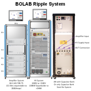
ISO 21498 HV Test System & Ripple Generator
BLS SU 600, Matrix Switching Unit
FIS 100-200 Fast Interrupt Switch 100V/200Amps
100-TS, 4-Quadrant Voltage Amplifiers 400 W - 54,000 W
100-TS, 4-Quadrant Current Amplifiers 400 W - 54,000 W
100-TS, VW 80000 / LV 124 : Battery test systems Test systems for 12 V | 24 V | 48 V batteries

100-TS, VW 80300 / LV 123 / LV 148 : HV Electric vehicle test systems
ISO 16750-2 Test System
ISO 7637-4 HV Test System
BLS 100-TS, For Low Voltage ISO 7637-2 & 16750-2 Transient testing

AN-ABCD-60, 60 Amp Artificial Network, EV HV Testing

400 - 6361, 2-Ch, 2.8MS/s, AnyWave Control Unit
400 - 6112, 2-Ch, 250kS/s, AnyWave Control Unit
Cx 10000-xxx-xxx, 1000V, 100 - 600 amp 10mF HV Capacitor Cabinet
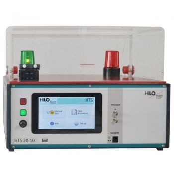
HTS 20-10, 20 kV, DC dielectric strength
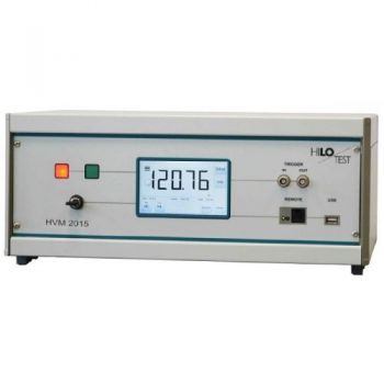
HVM 2015 High Voltage Meter 10kV, 20kV, ext. HVT 300kV

