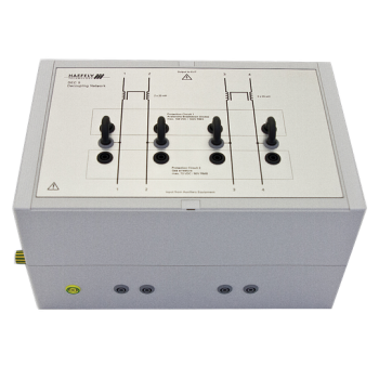
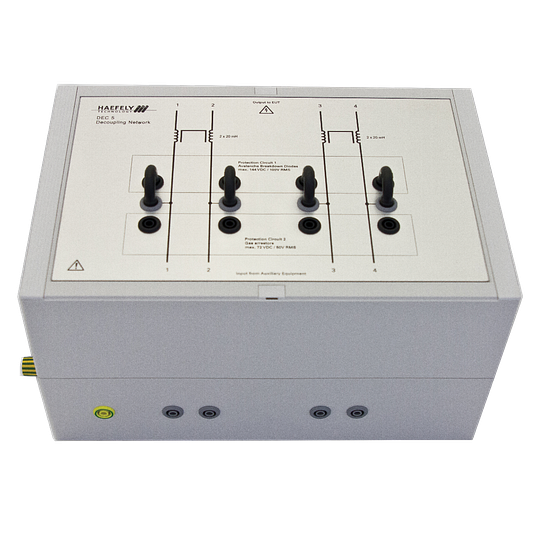
DEC 5 - 6.6 kV Decoupling Network for Symmetrical Lines
20 mH current-compensated inductors for symmetrical signal-line testing.
The Haefely DEC 5 separates auxiliary equipment from an EUT during transient immunity testing on unshielded symmetrical lines. It supports up to four wires and impulses up to 6.6 kV, using 20 mh current-compensated inductors; two inductors with two coils each. Coupling is performed by a separate network, allowing protection and decoupling to match the signal circuit.
PARTNER:
MARKETS:
CATEGORIES:
TEST STANDARDS:
Select Options/Sizes:

DEC 5 Datasheet V2026.06
SPECIFICATIONS
HAEFELY EMC ACCESSORIES
DEC 5 - 6.6 kV Decoupling Network for Symmetrical Lines
20 mH current-compensated inductors for symmetrical signal-line testing.

Overview and application
The Haefely DEC 5 separates auxiliary equipment from an EUT during transient immunity testing on unshielded symmetrical lines. It supports up to four wires and impulses up to 6.6 kV, using 20 mh current-compensated inductors; two inductors with two coils each. Coupling is performed by a separate network, allowing protection and decoupling to match the signal circuit.
- Manual protection selection makes the connected protection elements visible.
- The decoupling network does not generate or couple the test impulse; use it with a suitable coupling network and generator.
- Select EUT voltage, current and signal bandwidth together; the decoupling path can affect normal communication.
- Manufacturer-listed coupling networks: PCD 120, PCD 121 and PCD 122.
Technical specifications
| Specification | Details |
|---|---|
| Function | Decoupling and auxiliary-equipment protection; coupling supplied separately |
| Line type / capacity | Unshielded symmetrical data and control lines; up to 4 wires |
| Supported impulse shapes | 1.2/50 us - 8/20 us combination wave; 100 kHz ring wave; 10/700 us - 5/320 us telecom wave |
| Maximum impulse amplitude | 6.6 kV peak |
| Decoupling elements | 20 mH current-compensated inductors; two inductors with two coils each |
| Protection elements | Gas arrestors and avalanche breakdown diodes (ABDs) |
| Protection selection | Manual; operation without protection elements is also possible |
| EUT voltage with gas arrestors | Maximum 72 V DC or 50 V AC RMS |
| EUT voltage with ABDs | Maximum 144 V DC or 100 V AC RMS |
| Maximum EUT line current | 1 A |
| EUT signal bandwidth | Up to some 100 kHz / some 100 kBaud |
| Connections | Safety banana sockets |
| Dimensions (W x D x H) | 300 x 160 x 200 mm (11.8 x 6.3 x 7.9 in) |
| Weight | Approximately 9 kg net (19.8 lb) |
Included components
- DEC 5 decoupling network
- Cable set
- Four short-circuit bridges
- User manual
Generator, EUT, auxiliary equipment and other coupling/decoupling networks are separate system equipment unless explicitly included above.
Standards and system configuration
- IEC/EN 61000-4-5 Edition 2 Figure 14; Edition 3 Figure 10.
- IEC/EN 61000-4-12 Edition 2 Figure 12; Edition 3 Figure 9.
- ITU K.44:2003 Figures A.5-1 and A.6.1-1 through A.6.1-5.
Compare data-line coupling and decoupling networks
| Product | Function | Signal circuit | Test waveform | Key ratings |
|---|---|---|---|---|
| PCD 121 | Coupling | Symmetrical; 2 pairs / 4 wires | Combination wave | 6.6 kV; selectable gas arrestor / ABD coupling |
| PCD 126A | Coupling | 4 wires; asymmetrical surge; symmetrical or asymmetrical ring wave | Combination wave; 100 kHz ring wave | 6.6 kV; capacitors, ABDs, gas arrestors or direct |
| DEC 5 | Decoupling | Symmetrical; 4 wires | Combination, telecom and ring wave | 6.6 kV; 20 mH compensated; 1 A |
| DEC 6 | Decoupling | Symmetrical; 4 wires | Combination, telecom and ring wave | 6.6 kV; 200 ohm; 0.1 A |
| DEC 7 | Decoupling | Asymmetrical; 4 wires | Combination and ring wave | 6.6 kV; 20 mH uncompensated; 1.5 A |
| PCD-1000-4 | Coupling + decoupling | Balanced Ethernet; 1 / 2 / 4 pairs; 1000Base-T | Combination wave | 4 kV / 150 A surge; 65 V DC / 1 A line; IEEE 802.3af PoE |
Combination wave: 1.2/50 us voltage and 8/20 us current. Telecom wave: 10/700 us voltage and 5/320 us current. Ratings depend on the selected coupling/protection elements; review each product specification before configuring the system.
PCD 121 and PCD 126A provide coupling only. DEC 5, DEC 6 and DEC 7 provide decoupling/protection only. PCD-1000-4 combines both functions for high-speed Ethernet. IP4B is an EFT/burst clamp and is intentionally excluded from this matrix.
Related network options
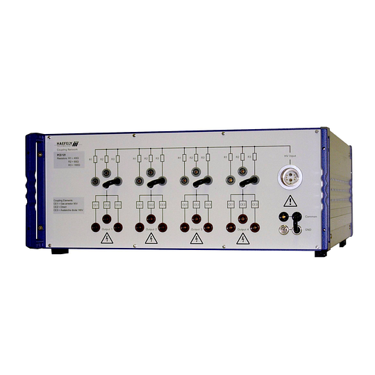 |
PCD 121
Combination-wave surge coupling for balanced data and control lines. |
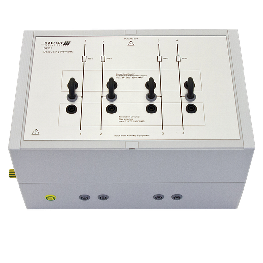 |
DEC 6
200 ohm resistors for symmetrical signal-line testing. |
Related test equipment
|
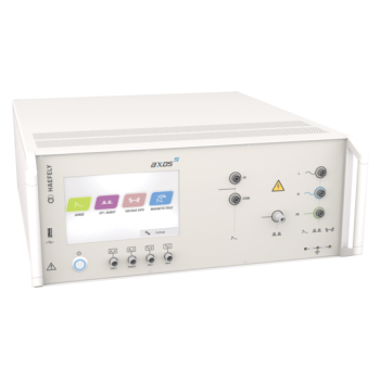
AXOS 5Select the installed EFT/burst or surge module required for the test. AXOS 5 does not provide ring wave or telecom wave. |
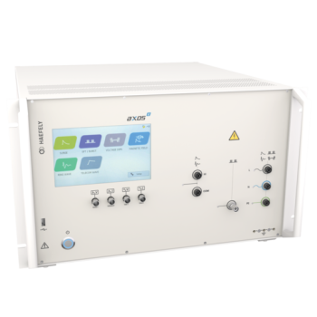
AXOS 8Configure the required surge, ring-wave, telecom-wave or EFT/burst modules. Stay within the accessory voltage and current ratings. |
Documentation
OTHER PRODUCTS IN THE SAME CATEGORY:
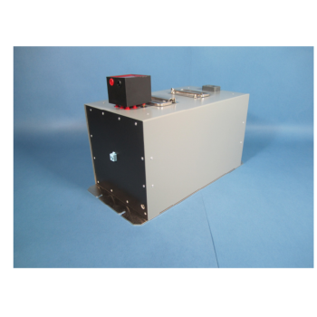
PCD-1000-4 - 4 kV Gigabit Ethernet and PoE Surge CDN
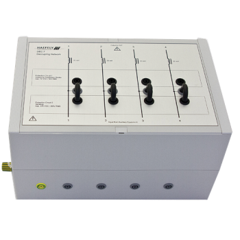
DEC 7 - 6.6 kV Decoupling Network for Asymmetrical Lines
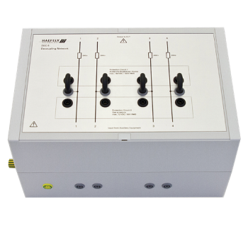
DEC 6 - 6.6 kV Decoupling Network for Symmetrical Lines
DEC 5 - 6.6 kV Decoupling Network for Symmetrical Lines
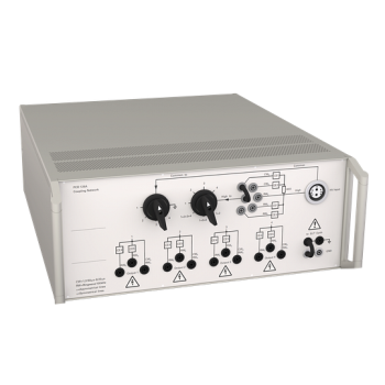
PCD 126A - 6.6 kV Surge and Ring-Wave Coupling Network
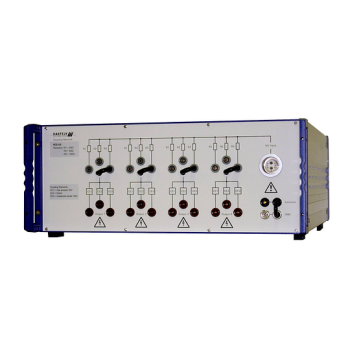
PCD 121 - 6.6 kV Surge Coupling Network for Symmetrical Lines
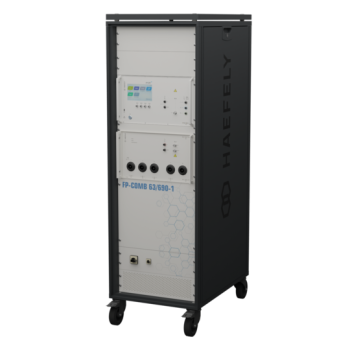
FP-COMB 63 / 125 / 200 A - 690 V AC Coupling / Decoupling Networks
FP-COMB 63 / 125 / 200 A - 1500 V DC Coupling / Decoupling Networks
FP-COMB 63 / 125 / 200 A - 690 V AC + 1500 V DC Test Networks (Duplicate)
FP-COMB 63 / 125 / 200 A - 690 V AC + 1500 V DC Test Networks
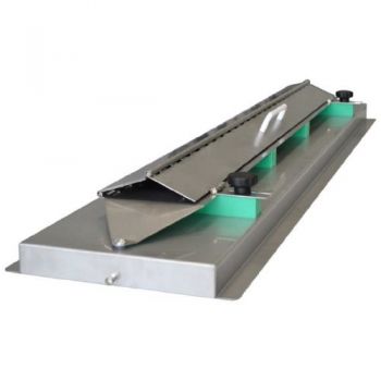
CAR CDN 2012 EFT/Burst Capacitive Coupling Clamp ISO

ESD-Static Dissipation Brush, referenced in EN 61000-4-2
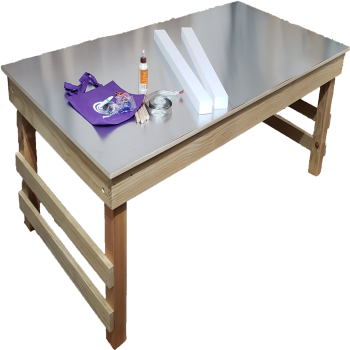
ESD Test Table Kit

CAR Cal Kit, Standard loads for Automotive Testing

EMC EPS 70x150cm Support- EUT support
EMC EPS Pad- 5x50x50 cm, EUT support

EMC EPS Block - 10 x 10 x 5 cm, EUT support

EMC PLA Block Lab kits, 10 x 10 x 5 cm

Absolute EMC Monopole Antenna Stand