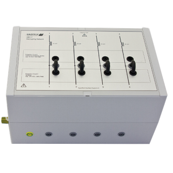
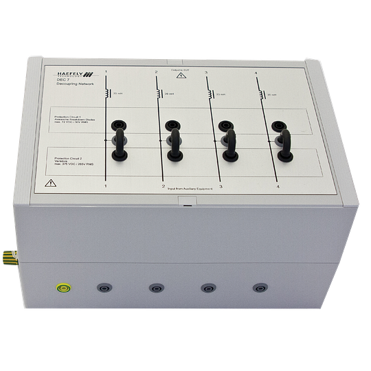
DEC 7 - 6.6 kV Decoupling Network for Asymmetrical Lines
20 mH inductors, not current-compensated for asymmetrical signal-line testing.
The Haefely DEC 7 separates auxiliary equipment from an EUT during transient immunity testing on unshielded asymmetrical lines. It supports up to four wires and impulses up to 6.6 kV, using 20 mh inductors, not current-compensated. Coupling is performed by a separate network, allowing protection and decoupling to match the signal circuit.
PARTNER:
MARKETS:
CATEGORIES:
TEST STANDARDS:
Select Options/Sizes:

DEC 7 Datasheet V2026.06
SPECIFICATIONS
HAEFELY EMC ACCESSORIES
DEC 7 - 6.6 kV Decoupling Network for Asymmetrical Lines
20 mH inductors, not current-compensated for asymmetrical signal-line testing.

Overview and application
The Haefely DEC 7 separates auxiliary equipment from an EUT during transient immunity testing on unshielded asymmetrical lines. It supports up to four wires and impulses up to 6.6 kV, using 20 mh inductors, not current-compensated. Coupling is performed by a separate network, allowing protection and decoupling to match the signal circuit.
- Manual protection selection makes the connected protection elements visible.
- The decoupling network does not generate or couple the test impulse; use it with a suitable coupling network and generator.
- Select EUT voltage, current and signal bandwidth together; the decoupling path can affect normal communication.
- Manufacturer-listed coupling networks: PCD 126A and IP6.2. Other decoupling elements are available on request.
The two EUT voltage ratings are reproduced without assigning them to varistors or ABDs; the datasheet does not identify that mapping.
Technical specifications
| Specification | Details |
|---|---|
| Function | Decoupling and auxiliary-equipment protection; coupling supplied separately |
| Line type / capacity | Unshielded asymmetrical data and control lines; up to 4 wires |
| Supported impulse shapes | 1.2/50 us - 8/20 us combination wave; 100 kHz ring wave |
| Maximum impulse amplitude | 6.6 kV peak |
| Decoupling elements | 20 mH inductors, not current-compensated |
| Protection elements | Varistors and avalanche breakdown diodes (ABDs) |
| Protection selection | Manual; operation without protection elements is also possible |
| EUT voltage ratings listed | Maximum 375 V DC / 265 V AC RMS, and 72 V DC / 50 V AC RMS. The datasheet does not map these limits to individual protection selections; confirm the intended configuration. |
| Maximum EUT line current | 1.5 A |
| EUT signal bandwidth | Up to some 100 Hz |
| Connections | Safety banana sockets |
| Dimensions (W x D x H) | 300 x 160 x 200 mm (11.8 x 6.3 x 7.9 in) |
| Weight | Approximately 6 kg net (13.2 lb) |
Included components
- DEC 7 decoupling network
- Cable set
- Four short-circuit bridges
- User manual
Generator, EUT, auxiliary equipment and other coupling/decoupling networks are separate system equipment unless explicitly included above.
Standards and system configuration
- IEC/EN 61000-4-5 Edition 2 Figures 11-13; Edition 3 Figure 9.
- IEC/EN 61000-4-12 Edition 2 Figures 9-11; Edition 3 Figure 8.
Compare data-line coupling and decoupling networks
| Product | Function | Signal circuit | Test waveform | Key ratings |
|---|---|---|---|---|
| PCD 121 | Coupling | Symmetrical; 2 pairs / 4 wires | Combination wave | 6.6 kV; selectable gas arrestor / ABD coupling |
| PCD 126A | Coupling | 4 wires; asymmetrical surge; symmetrical or asymmetrical ring wave | Combination wave; 100 kHz ring wave | 6.6 kV; capacitors, ABDs, gas arrestors or direct |
| DEC 5 | Decoupling | Symmetrical; 4 wires | Combination, telecom and ring wave | 6.6 kV; 20 mH compensated; 1 A |
| DEC 6 | Decoupling | Symmetrical; 4 wires | Combination, telecom and ring wave | 6.6 kV; 200 ohm; 0.1 A |
| DEC 7 | Decoupling | Asymmetrical; 4 wires | Combination and ring wave | 6.6 kV; 20 mH uncompensated; 1.5 A |
| PCD-1000-4 | Coupling + decoupling | Balanced Ethernet; 1 / 2 / 4 pairs; 1000Base-T | Combination wave | 4 kV / 150 A surge; 65 V DC / 1 A line; IEEE 802.3af PoE |
Combination wave: 1.2/50 us voltage and 8/20 us current. Telecom wave: 10/700 us voltage and 5/320 us current. Ratings depend on the selected coupling/protection elements; review each product specification before configuring the system.
PCD 121 and PCD 126A provide coupling only. DEC 5, DEC 6 and DEC 7 provide decoupling/protection only. PCD-1000-4 combines both functions for high-speed Ethernet. IP4B is an EFT/burst clamp and is intentionally excluded from this matrix.
Related network options
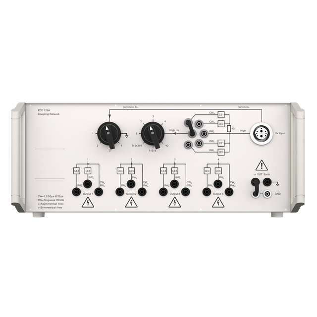 |
PCD 126A
Surge coupling for unbalanced lines, plus ring-wave coupling for balanced and unbalanced lines. |
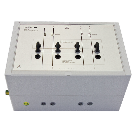 |
DEC 5
20 mH current-compensated inductors for symmetrical signal-line testing. |
Related test equipment
|
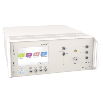
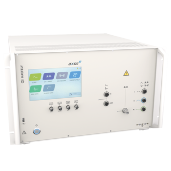
AXOS 5Select the installed EFT/burst or surge module required for the test. AXOS 5 does not provide ring wave or telecom wave. |
AXOS 8Configure the required surge, ring-wave, telecom-wave or EFT/burst modules. Stay within the accessory voltage and current ratings. |
Documentation
OTHER PRODUCTS IN THE SAME CATEGORY:
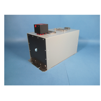
PCD-1000-4 - 4 kV Gigabit Ethernet and PoE Surge CDN
DEC 7 - 6.6 kV Decoupling Network for Asymmetrical Lines
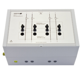
DEC 6 - 6.6 kV Decoupling Network for Symmetrical Lines
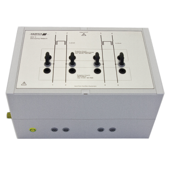
DEC 5 - 6.6 kV Decoupling Network for Symmetrical Lines
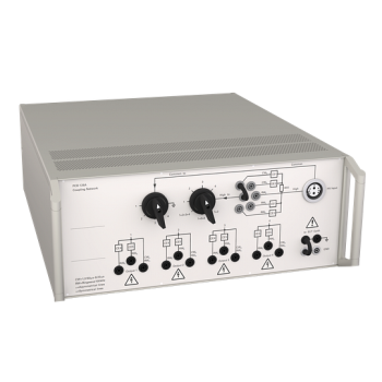
PCD 126A - 6.6 kV Surge and Ring-Wave Coupling Network
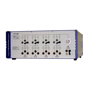
PCD 121 - 6.6 kV Surge Coupling Network for Symmetrical Lines
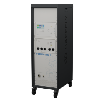
FP-COMB 63 / 125 / 200 A - 690 V AC Coupling / Decoupling Networks
FP-COMB 63 / 125 / 200 A - 1500 V DC Coupling / Decoupling Networks
FP-COMB 63 / 125 / 200 A - 690 V AC + 1500 V DC Test Networks (Duplicate)
FP-COMB 63 / 125 / 200 A - 690 V AC + 1500 V DC Test Networks
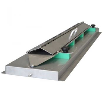
CAR CDN 2012 EFT/Burst Capacitive Coupling Clamp ISO

ESD-Static Dissipation Brush, referenced in EN 61000-4-2
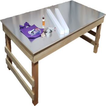
ESD Test Table Kit

CAR Cal Kit, Standard loads for Automotive Testing

EMC EPS 70x150cm Support- EUT support
EMC EPS Pad- 5x50x50 cm, EUT support

EMC EPS Block - 10 x 10 x 5 cm, EUT support

EMC PLA Block Lab kits, 10 x 10 x 5 cm

Absolute EMC Monopole Antenna Stand