Tutorial on Harmonics, Flicker and Related Immunity
Tutorial on Harmonics, Flicker and Related Immunity
Writen by: Mathieu van den Bergh CNS Inc. - USA
1. Introduction
Our utilities have to ensure the power quality and stability they bring into your home. Various disturbances occur, however, that are unavoidable. Because of harmonic current emissions from many products, the voltage is not always sinusoidal. Also, dips and even interrupts in the voltage occur on a regular basis. If a short circuit occurs – either in the home or in a nearby home, the voltage will dip or even be interrupted for a short time. When a big electric motor starts up, the inrush current causes the voltage to dip until the motor reaches nominal speed. When smaller electric motors start, such as for air conditioners, swimming pool pumps, floor grinders, etc. they also cause a (smaller) voltage dip.
In order to keep voltage distortion from increasing too much, electrical products must have limited harmonic current emissions. Also, electrical products must either have a “soft start” or have limited inrush, so as not to cause voltage dips that exceed a specified percentage – such as 4 % for most products, and values like 6 % for air conditioners etc.
In other words, electrical products cannot have emissions that are excessive. This is aimed at allowing the utilities to meet power quality standards, such as IEEE-519 in the US, and IEC/EN 50160 in most of Europe, with many countries like Japan, China, Brazil, and others, which have adopted their own national versions of IEC/EN 50160.
At the same time, electrical products must have the ability to handle the above common disturbances, either by being totally immune to them or by having a pre-determined and safe behavior to shut down and subsequently recover when a disturbance occurs.
The emission limits and immunity capability combined mean that a product must properly function in its electromagnetic environment. So, the product must meet EMC (Electro-Magnetic-Compatibility) requirements. This tutorial deals with most of the common emissions and immunity aspects, and the testing methods that have been developed to verify those products. Various standards have been developed that describe testing methods, and those will be explained.
2. IEC, EN, and national standards
The IEC Committee has developed a number of emissions and immunity standards. Most developed countries either have adopted the IEC standards, or have their own national versions, sometimes with modifications. Most of the standards for Europe are voted on by CENELEC – the body of the European Union (EU) that adopts or issues legal requirements. As an example, IEC 61000-3-2 limits harmonic emissions by electrical products, but the standard does NOT have the force of law. EN 61000-3-2 is the EU version of IEC 61000-3-2, and the EN version DOES HAVE the force of law, i.e. is a legal requirement to obtain the CE mark, which is a requirement to market products in the EU. Similarly, Japan has JIS-C 61000-3-2, and China has GB/T 14549, and Mexico has their national standard called ANCE NMX-J-550/3-2.
These standards generally apply only to electrical equipment that is to be connected to the public supply network. In other words, a large industrial facility with its own transformer connecting it to the grid, has a “private network” within the facility, and may opt for different requirements. Similarly, most hospitals have a private network within their buildings, although many medical equipment types are still tested to IEC standards. Also, DC networks are generally private networks, but the ripple on DC test is included in this tutorial, as it is a popular test, which is becoming more relevant as large data centers switch to cost saving DC supplies for their servers.
Also, there is the concept of unconditional and conditional or negotiated connection. Products < 16 A (per phase) that meet IEC 61000-3-2 and IEC 61000-3-3 can be connected anywhere - i.e. can be unconditionally connected. For higher power, however, a conditional connection usually applies, i.e. the installer or manufacturer must negotiate the connection to the public supply – with the applicable utility. So, IEC 61000-3-11 and IEC 61000-3-12 for products < 75 A (per phase) have provisions that put them in the conditional connection category. When we deal with IEC 61000-3-11 and IEC 61000-3-12, this will be further explained.
The following page shows a brief overview of selected standards and technical reports that are commonplace in EMC testing; The titles are abbreviated, and the reader can look up the full title if so required.
3. Selected IEC emissions & immunity standards and technical reports
- IEC 61000-3-2 Harmonic emission limits for products < 16 A (Edition 5, with amendments underway)
- IEC 61000-3-3 Voltage fluctuation & Flicker limits for products < 16 A (Edition 3, with amendments underway)
- IEC TS 61000-3-4 Technical Specification with emission limits for products > 75 A (1998)
- IEC 61000-3-11 Voltage fluctuation & Flicker limits for products < 75 A (Edition 2, with amendments underway)
- IEC 61000-3-12 Harmonic emission limits for products < 75 A (Edition 2, with amendments under way)
- IEC TR 61000-3-14 Technical report for higher power equipment connections to the LV network
- IEC 61000-4-7 Testing & Measurement Techniques- harmonics & inter-harmonics (Ed 2.1 with amendments underway)
- IEC 61000-4-11 < 16 A and IEC 61000-4-34 > 16 A Testing & Measurement Techniques- Voltage dips & interrupts (Ed. 2.1) for 4-11 with new revision underway
- IEC 61000-4-15 Testing & Measurement Techniques- Flickermeter (Ed. 2, with revision underway)
- IEC 61000-4-13 Testing & Measurement Techniques- Harmonics and inter-harmonics (Ed. 2.1)
- IEC 61000-4-14 Testing & Measurement Techniques- voltage fluctuations (Ed. 1.2)
- IEC 61000-4-17 Testing & Measurement Techniques- Ripple on DC power (Ed. 1.2)
- IEC 61000-4-27 Testing & Measurement Techniques- Unbalance in 3 phase systems (Ed. 1.1)
- IEC 61000-4-28 Testing & Measurement Techniques- Frequency variations (Ed. 1.2)
- IEC 61000-4-29 Testing & Measurement Techniques- Voltage dips & interrupts on DC supply (Ed. 1)
- IEC TR 61000-4-37 Calibration & Verification protocol for Harmonic Emission test systems (Ed. 1)
- IEC TR 61000-4-38 Testing & measurement techniques Test-Verification and calibration protocol for voltage fluctuations and Flicker test systems Ed. 1
- IEC TR 60725 Reference Impedance & Public Supply network impedance for testing < 75 A (Ed. 3.0)
- JIS-C 61000-3-2 : 2019 Japanese version of IEC 61000-3-2 with national deviations
- GB/T 14549 China – essentially equivalent to IEC 61000-3-2 Ed. 3.2
4. Standards and technical reports in progress
- IEC 61000-3-10 Emission Limits in the range from 2-9 kHz (harmonics & inter-harmonics)
- IEC 61000-3-16 Limits for harmonic currents produced by generating equipment (PV inverters)
- IEC 61000-3-17 Limits for flicker produced by generating equipment (PV inverters)
- IEC TR 61000-4-40 Testing & Measurement techniques Digital methods to measure power quantities on modulated or distorted signals)
- IEC TR 61000-3-18 Assessment of Network Characteristics to determine harmonic limits.
5. Background on the need to have product emission limits
The public supply voltage can be distorted when products have harmonic and/or inter-harmonic emissions. In the early and mid - 1980’s an increase in voltage distortion was observed in many areas. This prompted the development of IEC
555.2 (the predecessor of IEC 61000-3-2) with emission limits for household products. Also, as the public supply networks (and utilities) were privatized there was a need for a power quality (PQ) standard that the public supply should meet. This standard EN 50160 was approved by CENELEC in 1994. The current version dates from 2010.
In follow-up studies, the cumulative effect of the many electrical and electronic products became very evident. Below is a figure illustrating the 5th harmonic distortion in the London area (Eurelectric report 2003). As can be seen, the 5th harmonic exceeds the maximum permitted ( 95 percentile) 5 % per EN 50160. The maximum distortion occurs during the evening hours when people have their TV’s and PC’s etc. turned “on”. With a population of 8 – 9 million in the London area, the cumulative effect of millions of TV’s etc. is easily understood. The medium voltage and the high voltage distortion correlates very nicely with the distortion of the low voltage network, thus providing evidence that distortion “migrates up” and already provides a “base distortion” in areas that do not really contribute.
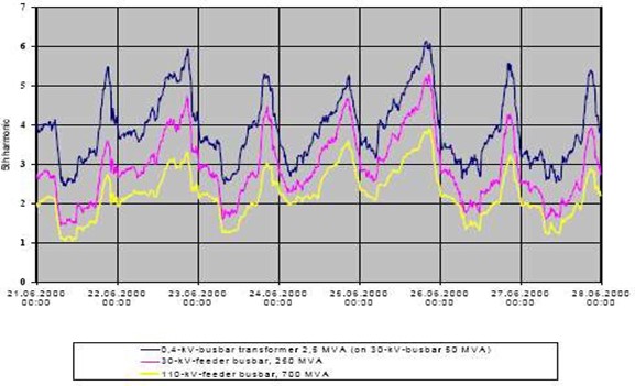
Figure 1 5th harmonic distortion on LV/MV/HV networks in the London area
Based on more measurements in various European countries, the harmonic emission standard was revised and updated to what we have today, being Edition 5 of IEC 61000-3-2 as of this writing. The harmonic emission limits in the standard are divided into 4 categories or test classes. Class-C includes lighting products and Class-D includes TV’s, monitors, and VSD refrigerators with a power level from 75 – 600 Watt. These two classes have the more restrictive emission limits, as there are millions of products that are “on” simultaneously. Class-B is the most relaxed test class for products with short time use, generally hand held. This includes hair dryers, curling irons, and the like. Class-A is the “catch all” for products that do not belong to either of Class-B, Class-C, or Class-D.
Page 10 shows the harmonic limits for the 4 test classes. For comparison, and for those that are interested in that earlier version, the table includes the original limits from IEC 555.2 for TV’s. It should be noted that the limits for Class-A and Class-B are fixed, irrespective of what power or current the tested product requires (up to 16 A / phase). The limits for Class-C and Class-D are proportional, i.e. are based on the current (Class-C) or power (Class-D)
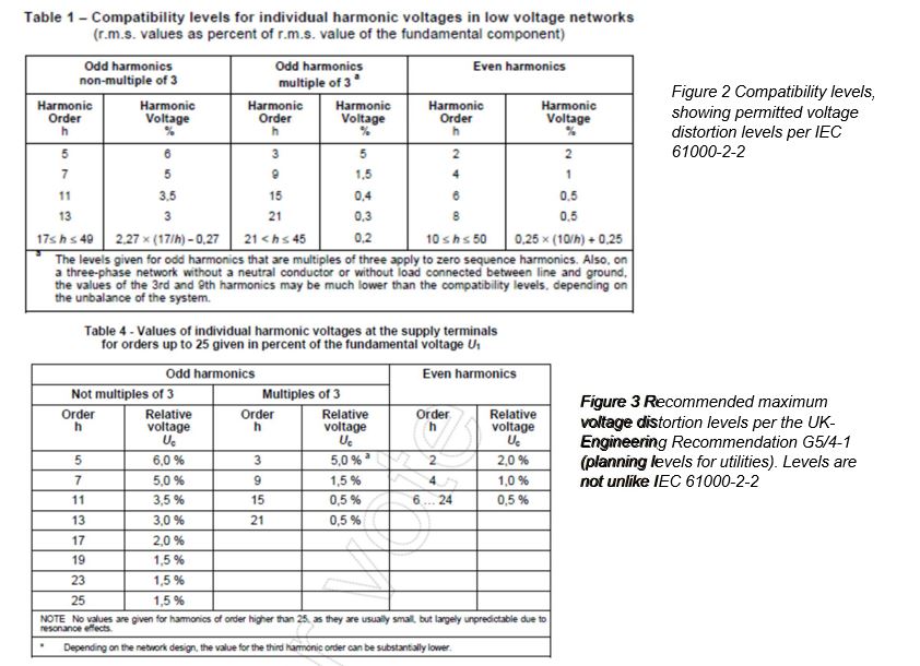
6. Compatibility limits
The Compatibility Limits are used in the process of determining harmonic emission limits. Various standards specify what the maximum permissible voltage distortion on the public supply network can be. This is basically a product quality standard, with the product being the electricity supply. As the utilities in Europe were privatized, this quality standard became more important, as utilities have to adhere to the limits. Provided the voltage distortion remains below the compatibility levels, it is unlikely that problems with electrical equipment will occur. The utilities use the compatibility in their planning, to dimension network elements, such as transformers, feeders, and local lines.
One can derive the estimated voltage distortion levels at the local premises on the basis of current harmonics and the system impedance at the location. For example, for H5 and the European Reference impedance with (0.4 + j 0.25 ?) @ 50 Hz, a 5th harmonic current of 1.14 Amp would produce a harmonic voltage of 1.5 Volt i.e. ~ 0.65 %. For Class-B where
1.5 x the Class-A limit is permitted, the 1.71 Amp permitted harmonic would produce about 1 % voltage distortion for just H5. Given the cumulative effect as illustrated in Fig. 1, the general rule is to allocate no more than 25 % of the compatibility levels to local premises.
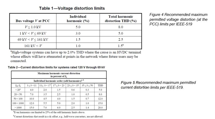
Below are the compatibility levels for the European area. England has its own G5/4-1 specification for planning levels. IEEE-519 also includes recommended distortion levels. Although IEEE-519 does not have the force of law, it is generally adhered to in the USA. Generally, the distortion is measured at the Point of Common Coupling (PCC).
It should be noted that the impedance at the local level in Europe is generally around 60 – 70 % of the Reference Impedance values, although in rural areas with overhead power lines, the impedance can even be higher than the Reference Impedance values of (0.4 + j 0.25 ?). IEC TR 60725 provides more information on impedance levels, and so does a report which is referenced later. Below is a table with the measured impedance in various countries.
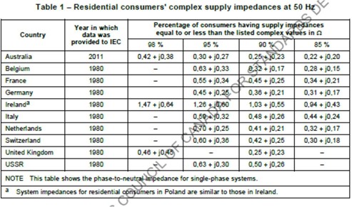
Figure 6 System impedance in various countries (2000 data).
Several countries in Asia, including Korea and China have a system impedance that is not unlike Europe. The Japanese system impedance is slightly lower, and the US and Canada have a system impedance that is 1/3rd to ½ the European impedance. The North American system has longer MV lines and shorter LV lines, which helps to
reduce system impedance. Given that electrical equipment needs about double the current for the 120 Volt system vs. the 220-230 Volt in Korea, China, and Europe, it is rather beneficial (necessary) to have the lower system impedance in North America. Because of discussion in the IEC working group, CNS Inc. undertook the task of characterizing the system impedance in various countries, and issued a report. This report was part of the proceedings of one of the IEC committee meetings, and was also used when IEC TR 60725 was revised to its current status. The report is available from CNS upon request.
IEC 61000-3-2 Harmonic Emission Limits
| Harmonic no. (n) | Class - A limits (both standard s) | Class-B limits (both standards) | Class-C limits IEC1000-3-2 only | Class-D limits IEC1000-3-2only | IEC555.2limits for TVreceivers (> 165Watt) |
| A rms | A rms | % of fundament alnote:8 is the PF | mA/Watt of input power (75 - 600 W) | note: max dc current< 0.05 A A rms | |
| 2 | 1.080 | 1.620 | 2 % | n/a | 0.300 |
| 3 | 2.300 | 3.450 | 30 x 8 % | 3.4 mA/Watt | 0.800 |
| 4 | 0.430 | 0.645 | n/a | n/a | 0.150 |
| 5 | 1.140 | 1.710 | 10 % | 1.9 mA/Watt | 0.600 |
| 6 | 0.300 | 0.450 | n/a | n/a | n/a |
| 7 | 0.770 | 1.155 | 7 % | 1.0 mA/Watt | 0.450 |
| 8 | 0.230 | 0.345 | n/a | n/a | n/a |
| 9 | 0.400 | 0.600 | 5 % | 0.5 mA/Watt | 0.300 |
| 10 | 0.184 | 0.276 | n/a | n/a | n/a |
| 11 | 0.330 | 0.495 | 3 % | 0.35 mA/Watt | 0.170 |
| 12 | 0.153 | 0.230 | n/a | n/a | n/a |
| 13 | 0.210 | 0.315 | 3 % | 0.296mA/Watt | 0.120 |
| Even 14 -40 | 1.84 /n | 2.760 /n | n/a | n/a | n/a |
| Odd 15 -39 | 2.25 /n | 3.338 /n | 3 % | 3.85/n(mA/Watt) | 1.5 /n(Amp) |
Figure 7 harmonic emission limits per IEC 61000-3-2
Class-A and B are fixed, with the Class-B limits simply being 1.5 x the Class-A limits.
Class-C – the limits are proportional to the product input current – for products > 25 Watt ( > 35 Watt for Japan ).
- Class-C products from 5 – 25 Watt have 3 test criteria, and the product passes if it meets any of the 3; 1: Meet the Class-D limits (proportional to power – see the 5th column)
- 2: Meet the special waveform requirement (see next page)
- 3: Meet the I-THD limit of 70 % with limits of 35 % for H3, 25 % for H5, 30 % for H7, 20 % for H9 and H11, and a limit of 5 % for the 2nd harmonic.
Class-D – The limits are proportional to the product’s power, but only in the range from 75 – 600 Watt. At 600 Watt, the Limits are about equal to the Class-A limits, which then apply for higher power levels.
7. IEC 61000-3-2 Class-A and B emission limits
As mentioned earlier, The Class-A and Class-B limits are fixed (see the table in Figure-7 and the “Harm Limit column in Fig. 11 below). Basically, the limits for Class-A were derived from the early compatibility levels. As explained in the previous section, the compatibility or planning levels are voltage distortion levels in percent for individual harmonics, where it is expected that no problems are caused for products that are connected to the network.
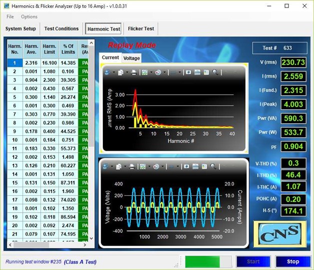
Figure 8 Test screen of a Class-A test with limits shown in the top graph (yellow is 100 % limit, red is 150%)
For all harmonic emission tests, the average of harmonics must be below the (100 %) “Harm Limit” The levels of individual 200 ms (low pass filtered) measurement windows must be below 150 % of the limit. The individual 200 ms harmonics measurement data goes through a 1.5 sec time constant low pass filter, so as to minimize the impact on harmonics from switching events, and rapid fluctuations. A 1.5 sec filter low pass means that any new value is multiplied by 0.125 and added to the previous average x 0.875. Thus, the harmonics have to be present for several seconds before the average reaches a higher level. A product can fail the test because the 100 % limit is exceeded on average, or because a particular measurement window fails the 150 % limit.
8. Class-A Fail Test, the 90 / 200 % rule, and the POHC allowance
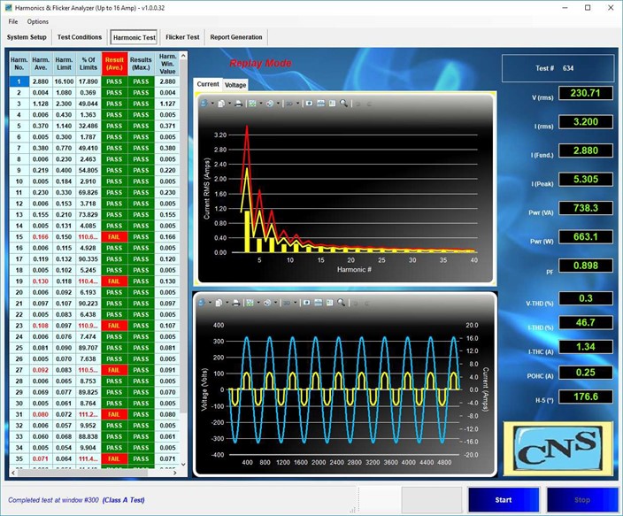 Figure 9 Test screen of a Class-A test with several harmonics exceeding the 100 % limits.
As follows from the above screen shot, several harmonics (H15-19-23-27-31-35-39) exceeded the limits. All harmonics pass the 150 % limit. The standard permits Class-A to have up to 200 % of the limit, provided that the average harmonics are all below 90 %. This accommodates products that have short – high – excursions, but have on average low emissions. Also, for Class-A, there is a Partial Odd Harmonic Current (POHC) allowance. This allows individual odd harmonics from 21 – 39 to exceed the 100 % limit, provided that the rms value of H21-39 is below the POHC limit, and the harmonics are < 150 %. The POHC limit is computed by taking the rms of the odd harmonic limits from H21-39, and it is 0.251 A for Class-A.
Some software, such as the program shown above, automatically applies the 90/200 % rule in the event that the 150 % limit is exceeded. Also, the POHC is automatically taken into consideration.
9. Class-C Limits for lighting > 25 Watt (35 Watt in Japan)
The limits for Class-C are proportional to the current of the lighting product. For example, the limit for H-5 is 10 % of the fundamental current component (i.e. 69 mA in this case). The limit for H3 is equal to 30 % x PF, so for a product with a PF of 0.9, the limit would be 27 %.
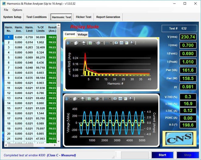
Figure 10 Test screen of a Class-C test with several harmonics just below the limit.
|
Harmonic order h |
Maximum permissible harmonic current expressed as a percentage of the input current at the fundamental frequency % |
|
| 2 | 2 | |
| 3 | 30 × ? a | |
| 5 | 10 | |
| 7 | 7 | |
| 9 | 5 | |
| 11 ? h ? 39 | 3 | |
| (odd harmonics only) | ||
| a | ? is the circuit power factor. | |
Figure 11 Class-C limits for products > 25 Watt.
10. Class-C Limits for lighting from 5 – 25 Watt (35 Watt in Japan)
Low power lamps such as CFL’s and LED based products are extremely cost sensitive. Because of their volume in use, and because these products are normally “on” simultaneously for many hours, emission limits are still necessary for these products, but there are several relaxations.
One set of relaxations, is based on the so-called “shark” waveform. Another allows up to 70 % THD, and a third allowance are the Class-D limits. An example of a 12 Watt LED lamp that meets those Class-D limits is shown below (left graph shows the harmonics and the limit lines, right graph shows the waveform).
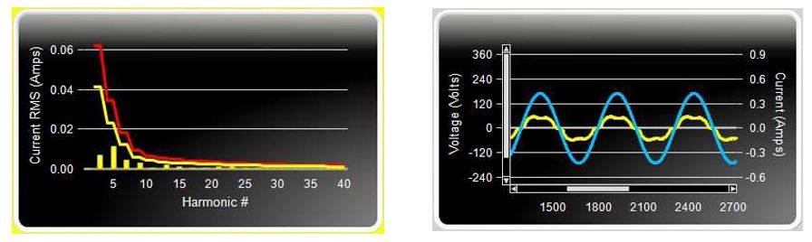
Figure 12 Example of a 12.2 Watt lamp that meets the Class-D limits.
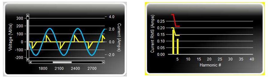
Figure 13 Example of a 24.7 Watt lamp that meets the special “shark fin” waveform requirement.
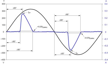
Figure 14 Special waveform for lighting from 5 – 25 Watt
The special waveform specification requires that the peak current happens before 65 deg (245 deg) and that there is at least 5 % current flow at 60 and 90 deg (240 – 270 deg).
If the product has low harmonics, or the special waveform, as shown to the left, it either doesn’t “accumulate” harmonics in the network, or partly compensates for tablet and phone chargers, and many other low power products that have no harmonics mitigation.
The third relaxation is that the product must have a I-THD < 70 %, with max percentage for individual harmonics (see page 9 for specific limits)
11. IEC 61000-3-2 Class-D emission limits
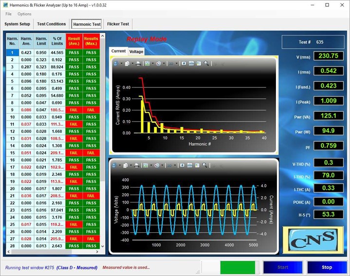
Figure 15 A Class-D test with harmonic emissions that fail the limits
|
Harmonic order h |
Maximum permissible harmonic current per watt mA/W |
Maximum permissible harmonic current A |
| 3 | 3,4 | 2,30 |
| 5 | 1,9 | 1,14 |
| 7 | 1,0 | 0,77 |
| 9 | 0,5 | 0,40 |
| 11 | 0,35 | 0,33 |
|
13 ? h ? 39 (odd harmonics only) |
3,85 h |
See Table 1 |
Figure 16 Class-D limit table
The limits for Class-D are proportional to the product power. For example, H3 has 3.4 mA / Watt.
As is evident from the above screenshot, some harmonics even exceed the 150 % limit.
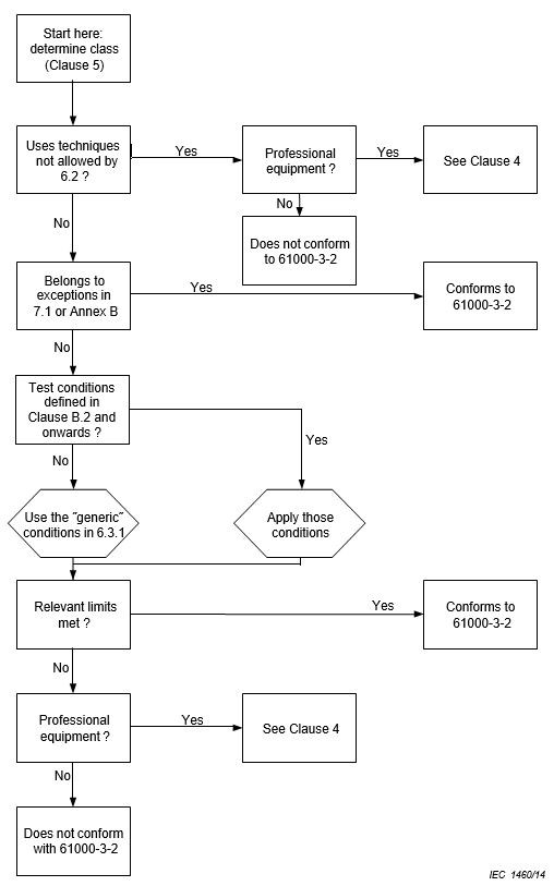
12. Selecting a test class & conditions per IEC 61000-3-2
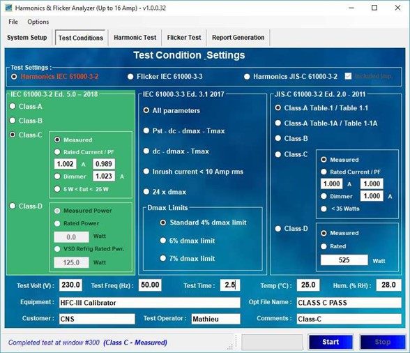 Figure 17 Selecting one of the test classes
The first step when running a harmonics test per IEC 61000-3-2 is to select the test class and duration. As explained on page 9 and the following pages for each product test, there are 4 test classes. Unless the product falls in the Class-B, C, or D category, the user selects Class-A.
Class-B is reserved for portable tools (handheld electrical products) and non-professional arc welding equipment.
Class-C applies to all lighting, but there are a couple sub-choices. Does the user or manufacturer have a specific rated current? If yes, that current and power factor can be entered, and will be the basis for limit calculation, unless the actually measured current is outside the range of 90 – 110 % of the rated value. In that case, the measured value needs to be used. If the product is in the range from 5 – 25 Watt, the user selects that test option. Also, for a dimmer there is a special provision. For dimmers, the user can enter the current that is measured when the dimmer is set to maximum power (light). That current is then used to calculate the limits. Also, for dimmers intended for incandescent lamps, the user must set the dimmer to 90 degrees (+/- 5 deg).
Class-D is for TV’s, monitors, PC’s, and VSD based refrigerators in the power range from 75 – 600 Watt. For PC’s, TV’s, and monitors, the user can also select “Rated Power” – again provided that the actually measured power is within 90 – 110 % of the rated value. For VSD refrigerators, the test duration is 1 hour. The appliance is empty, the door opened for 60 seconds (+/- 6 sec), and then the rated power is calculated using the formula in Figure 18, where Im is the maximum observed current when the VSD refrigerator is operated at the rated voltage.
Figure 18 Formula to determine rated power for VSD refrigerators Pi = 0,78 x Im x Ur
The test condition selection flow chart for IEC 61000-3-2
13. IEC 61000-3-12 harmonic emission limits < 75 Amp
The concept behind IEC 61000-3-12 for products up to 75 Amp (per phase) is a little different. Whereas IEC 61000-3-2 permits an unconditional connection for products that meet the limits, IEC 61000-3-12 has variable limits – that in principle result in a conditional connection. For a connection at a point where the system impedance is lower, higher harmonic limits are permitted. Also, the standard has separate tables for single phase and 3 phase products, and two more tables that meet certain criteria, such as the phase angle of the 5th harmonic.
Table-2 Limits for single-phase or non-balanced 3 phase equipment
|
Minimal Rsce |
Admissible individual harmonic current Ih/Iequ a % |
Admissible harmonic parameters % |
||||||
| I3 | I5 | I7 | I9 | I11 | I13 | THC/ Iequ | PWHC / Iequ | |
| 33 | 21,6 | 10,7 | 7,2 | 3,8 | 3,1 | 2 | 23 | 23 |
| 66 | 24 | 13 | 8 | 5 | 4 | 3 | 26 | 26 |
| 120 | 27 | 15 | 10 | 6 | 5 | 4 | 30 | 30 |
| 250 | 35 | 20 | 13 | 9 | 8 | 6 | 40 | 40 |
| ? 350 | 41 | 24 | 15 | 12 | 10 | 8 | 47 | 47 |
|
The relative values of even harmonics up to order 12 shall not exceed 16/h %. Even harmonics above order 12 are taken into account in THC and PWHC in the same way as odd-order harmonics. Linear interpolation between successive Rsce values is permitted. |
||||||||
| a Iequ = rated current; Ih = harmonic current component. | ||||||||
Figure 19 Harmonic limits for single-phase or other than balanced 3 phase products
The Rsce stands for Short Circuit Current Ratio, which is the Short Circuit Power (Ssc) divided by the equipment power. So, as the Rsce increases (meaning the connection can deliver more power – or conversely – has a lower impedance, the limits increase. This can easily be understood. For example, a 5 amp 3rd harmonic that is present in a connection with an impedance of 0.4 ? will cause a harmonic voltage of 5 x 0.4 = 2.0 V-rms. If, however, the connection has an impedance of ?, the harmonic voltage is only 0 V-rms. The user tries to “PASS” the product test with a lower Rsce, and if the limits are exceeded, he/she selects a higher Rsce until the limits are met. The consequence, however, is that the equipment documentation has to call for the higher Ssc. So, the equipment manufacturer must;
- determine the minimum value of Rsce for which the limits given in Tables 2, 3 or 4 are not exceeded,
- declare the value of the short-circuit power Ssc corresponding to this minimum value of Rsce in the instruction manual,
- and instruct the user to determine, in consultation with the distribution network operator if necessary, that the equipment is connected only to a supply of that Ssc value or
Obviously, the lower Rsce the lower the Ssc the manufacturer can declare, and the more connections will be suitable for the equipment. So, the connection is conditional upon having a high enough Ssc.
Whereas one simply selects the test class for harmonics per IEC 61000-3-2, one must first select which table to use, i.e. Table-2, Table-3, Table-4 or Table-5, and then select what Rsce level to use, which in turn determines the limits. The test setup is illustrated on the next page, where the user selects a Table-2 test, with an Rsce of 33.
For equipment that meets the limits with an Rsce of 33, the user can simply state;
”Equipment complying with IEC 61000-3-12”.
For equipment that requires a higher Rsce, the above listed conditions / product information need to be provided.
14. IEC 61000-3-12 harmonic emission test setup
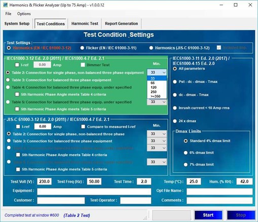
Figure 20 Test setup for a Table-2 test with an Rsce of 33
|
Minimal Rsce |
Admissible individual harmonic current Ih/Iequ a % |
Admissible harmonic parameters % |
||||
| I5 | I7 | I11 | I13 | THC/Iequ | PWHC/Iequ | |
| 33 | 10,7 | 7,2 | 3,1 | 2 | 13 | 22 |
| 66 | 14 | 9 | 5 | 3 | 16 | 25 |
| 120 | 19 | 12 | 7 | 4 | 22 | 28 |
| 250 | 31 | 20 | 12 | 7 | 37 | 38 |
| ? 350 | 40 | 25 | 15 | 10 | 48 | 46 |
|
The relative values of even harmonics up to order 12 shall not exceed 16/h %. Even harmonics above order 12 are taken into account in THC and PWHC in the same way as odd order harmonics. Linear interpolation between successive Rsce values is permitted. |
||||||
| a Iequ = rated current; Ih = harmonic current component. | ||||||
Figure 21 Limits for balanced 3- phase equipment per Table-3
Note that there are no limits for H3 and H9, as balanced 3 phase equipment has in principle no odd triplen harmonics ( 3 – 9 – 15 – 21, etc).
As with Table-2, the harmonic current emissions from H14 – H40 are taken into account in the THC and PWHC parameters in % of I-rms, which are computed using ;
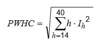
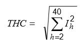
15. IEC 61000-3-12 Table-2 Test screen
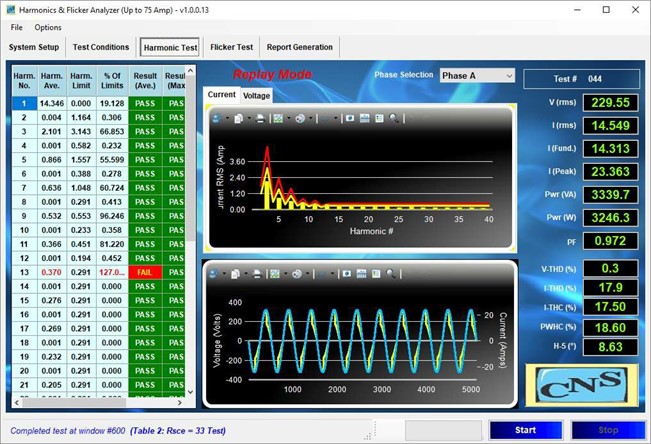 Figure 22 IEC 61000-3-12 test per Table-2 with a Rsce of 33
As follows from the above test screen, harmonic 13 fails the limit by 27 %. If the user selects an Rsce of 66, the limit for H13 will be 3 % instead of the 2 % that applies for an Rsce of 33 (i.e 0.437 A). So, if the user defines a test for Rsce 66 for this equipment, it will pass (see the limits in the table per Figure 19)..
For equipment that is rated > 16 Amp, but where the actual current is below 16 Amp (as in the above case) the user can opt the test per the applicable IEC 61000-3-12 limit table and Rsce, or test per IEC 61000-3-2 Class-A. In this case, it would not help to test per Class-A, as many of the higher order harmonics from H11 and up, would fail the Class-A limits. Therefore, testing with an Rsce of 66 is the best way to obtain a “PASS” for the product in question.
So, the general approach is to try to have the product PASS for the lowest Rsce.
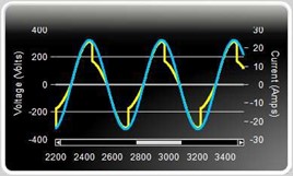
Figure 23 Zoomed in version of the waveform
IEC 61000-3-12 also has Table-4 and Table-5, with slightly relaxed limits for 3 phase equipment.
Those tables can be used if the product has a 5th harmonic that is in the range from 90 – 150 degrees (Table-4) or 150 – 210 degrees (Table-5). Therefore, the analysis per IEC 61000-3-12 includes the 5th harmonic phase angle, 8.63 degrees in this case. Therefore, tables-4 or 5 are not applicable for this EUT. The “zoomed in” version of the current waveform (generated with a HFC-III calibrator) is shown in Figure 23.
16. IEC 61000-3-3 Voltage fluctuation and Flicker testing < 16 A
Electrical products may produce load fluctuations. Examples are microwave ovens, welding equipment, water heaters, laser printers, etc. These load fluctuations in turn cause voltage fluctuations at the point of common coupling (PCC), where other customers are also connected to, which also “see” these fluctuations and thus may cause light flicker. The original intent of IEC 61000-3-3 was to reduce the light flicker from incandescent lamps, caused by voltage these fluctuations. A large scale test was done to establish the sensitivity of humans to light fluctuations. Voltage fluctuations of various amplitudes and frequencies were applied to a 60 Watt light bulb. The Pst = 1 curve (see figure 25) resulted from voltage and frequency combinations where about half the people perceived the resulting light flicker. Some have criticized the continued use of the 60 Watt light bulb, but it has become the “reference method”.
The Pst is basically a measurement of the irritation that voltage fluctuations can cause. In some cases, with a very rapid fluctuation rate, people may not even realize why they get a headache. The Plt parameter is calculated from multiple (normally 12) successive 10 minute Pst measurements.
The test setup is as shown below (for a 3 phase connection). The RA and jXA in the 3 phases, and RN and jXn in the neutral, in conjunction with the power source impedance, form the test or Reference Impedance. As the Equipment Under Test (EUT) draws current, the voltage at its input terminals (measured by “M”) will drop, more or less proportional to the EUT current. That voltage drop can be a “steady state” voltage drop, it can fluctuate, or be a combination of these, depending on the EUT’s behavior.
The supply consisting of the supply voltage generator G impedance and reference impedance Z must have the
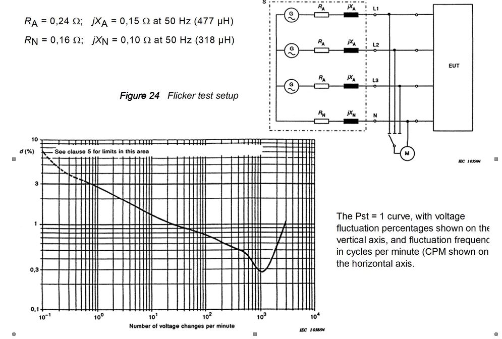
Figure 25 The Flicker sensitivity curve by frequency & amplitude
The Pst and Plt parameters
The Pst and Plt calculations are based on individual voltage samples. For example, a 10 kHz sampling rate means that 10,000 samples are processed every second. The Flicker meter demodulates the voltage signals, and then performs low pass and high pass filtering, to remove the 230 Volt 50 Hz (or 120 V / 60 Hz) Volt component and higher frequencies that are not perceived by humans. Subsequently, the signals go through a weighting filter that follows the “sensitivity” curve shown in Figure 25. The weighting filter is implemented as a two dimensional (Laplace) transfer function (see also the section on IEC 61000-4-15).
Test have shown that some fluorescent and LED lamps are more sensitive to voltage fluctuations, but properly designed products are usually less sensitive. The faster time constant of LED’s and CFL’s would cause more light flicker if the driving circuit is not designed correctly. The lighting industry has developed a light flicker meter, based on the IEC flicker meter, and it is used to make sure that lighting products are not more sensitive than the 60 Watt bulb.
So, as follows from the curve in Figure 25, a 1 % voltage fluctuation that is repeated 25 times per minute will result in a Pst of 1. The most sensitive point is at 1052 voltage changes per minute, and a fluctuation level of 0.276 % will result in a Pst of 1.0. At very low frequencies like 2 CPM, the voltage fluctuation needs to be 4.5 % to get a Pst of 1.00. As follows from the limits below, values exceeding 4 % are “caught” through the directly measured parameters.
The various blocks of the Flicker meter are illustrated below. It is a relatively complicated instrument, and the details go beyond this tutorial. For those wanting more information, IEC 61000-4-15 Ed. 2 provides every detailed one can wish for.
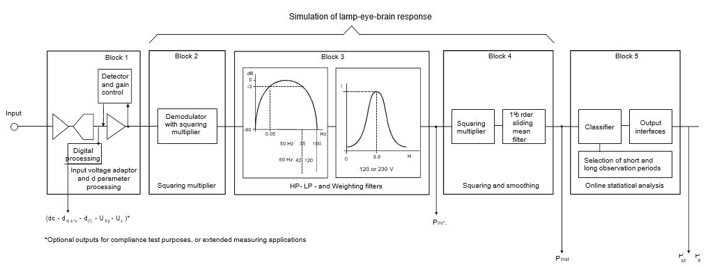
Figure 26 The Flicker meter functional diagram (per IEC 61000-3-3 and IEC 61000-4-15)
Pst is normally evaluated over a 10 minute observation period, and the Plt parameter is computed from successive Pst values through a cubed averaging algorithm (see below). For some products, with longer operating cycles, the test duration may exceed 2 hours. For products with shorter operating cycles, the test will be 2 hours or less, and can be as short as 10 minutes. Although some Flicker meters also show the instantaneous Psti a test of 10 minutes is required to obtain the Pst value. The Plt is normally computed over 12 ea. Pst periods, i.e. 2 hours, but for equipment with an operating cycle that is less than 2 hours, the “remaining” Pst values can be set to “zero”. So, the “N” in the Plt formula below is normally equal to 12. The standard defines limits for the directly measured parameters, as well as for Pst and Plt.
Figure 27 The cubed averaging for Plt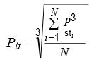
The directly measured flicker parameters
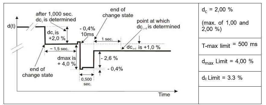
Figure 28 The directly measured parameter diagram
For the directly measured parameters, the rms voltage is computed every half cycle (every 10 ms for 50 Hz systems), i.e. 100 half cycles per second for a 50 Hz test. So, for a 10 minute test, there are 600 x 100 = 60,000 half cycle rms values.
The successive rms values are evaluated in percent of the nominal test voltage
“dc” is the steady state voltage drop, and is determined if at least 100 half cycle rms voltage values are within ± 0.2 % The dc percentage is measured vs. the previously established steady state voltage.
“dmax” is the maximum (short term) voltage drop, usually due to inrush current of the EUT
“T-max” is the duration that the voltage at the EUT terminals drops below 3.3% vs the last steady state voltage.
Because there can be multiple changes during a test, the maxima are “peak hold” values
The IEC 61000-3-3 voltage fluctuation and Flicker limits.
- the value of Pst shall not exceed 1,0;
- the value of Plt shall not exceed 0,65;
- Tmax, the accumulated time value of d(t) with a deviation exceeding 3,3 % during a single voltage change, shall not exceed 500 ms;
- the maximum relative steady-state voltage change, dc, shall not exceed 3,3 %;
- the maximum relative voltage change dmax, shall not exceed:
- 4 % without additional conditions;
- 6 % for equipment which is switched manually, or switched automatically more frequently than twice per day, and also has either a delayed restart (the delay being not less than a few tens of seconds), or manual restart, after a power supply
- 7 % for equipment which is:
- attended whilst in use (for example: hair dryers, vacuum cleaners, kitchen equipment such as mixers, garden equipment such as lawn mowers, portable tools such as electric drills), or
- switched on automatically, or is intended to be switched on manually, no more than twice per day, and also has either a delayed restart (the delay being not less than a few tens of seconds) or manual restart, after a power supply
The IEC 61000-3-3 Flicker measurement screen
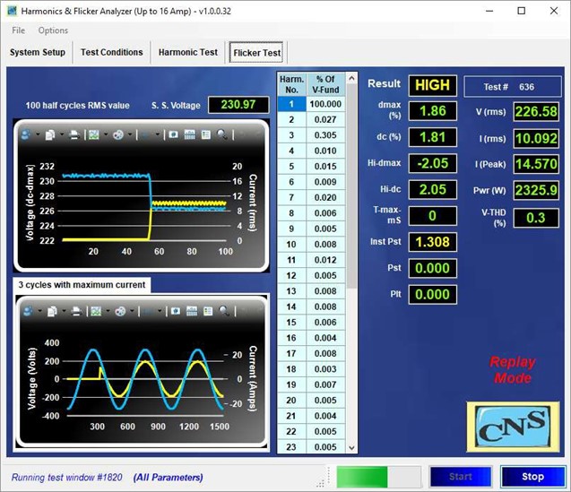
Figure 29 The Flicker measurement screen
The top graph in Figure 29 illustrates the 100 half cycle voltage values (blue trace), as well as the current flow (yellow trace). The screen shot was made at the moment the load (EUT) was turned “On” and the current jumped to about 10.1 A-rms. As a net result, the voltage dropped about 4.3 V-rms, or about 1.87 %. The highest dmax that occurred was 2.05.
It will be obvious that the voltage drop is proportional to the current AND to the impedance values (see figure 24). So, if the impedance is too high or too low, the Flicker measurement will also be too high or too low. The display does not show a value for Pst as yet, because the test is only partially completed, but the instantaneous Pst up to that moment is 1.308, hence the yellow color as the Inst Pst exceeds the 1.00 limit. If the Pst value persists until the end of the 10 minute period, the Pst will turn read, and the result will change to FAIL
The IEC 61000-3-3 standard requires that the test voltage is reasonably “clean” and the voltage distortion is < 3 %, so that parameter is shown in addition to the voltage, current, and power.
Also, the standard requires that the power source contributes less than 0.4 to the Pst. This can easily be tested by setting the Reference Impedance to “bypass” and running the same Flicker test (as also specified in Test no.1 of IEC TR 610004-38.
The Flicker test configuration screen
The user selects the test that fits the test conditions specified in the standard. For short cyclic equipment ( ? 10 minutes), the Pst-dc-dmax- Tmax choice applies. For long cyclic equipment all parameters is the applicable choice.
For so-called brown goods (audio – stereo – TV, etc.) only dc-dmax-Tmax are required.
20 Amp Inrush current and stable current within ± 1.5 Amp thereafter
The standard also permits a somewhat simplified method to determine compliance. For voltage changes caused by manual switching, equipment is deemed to comply without further testing if the maximum
r.m.s. input current (including inrush current) evaluated over each 10 ms half-period between zero-crossings does not exceed 20 A, and the supply current after inrush is within a variation band of 1,5 A.
For some equipment the 24 x dmax procedure (see be) can be used.
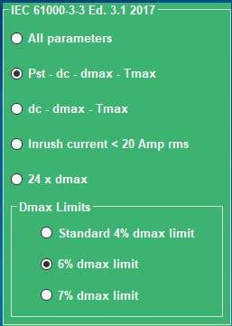
Figure 30 The Flicker measurement screen
The 24 x dmax test
Also, there is a “24 x dmax” procedure for manually switched products, air conditioners, dehumidifiers, heat pumps, and commercial refrigerating equipment. The test sequence is as follows;
start a measurement;
switch on the EUT (to create a voltage change);
let the EUT operate as long as possible under normal operating conditions during a measuring time interval of 1 min;
switch off the EUT before the end of the 1 min measuring time interval and make sure that all moving parts inside the EUT come to standstill and that any dmax mitigation devices have had time to cool to the ambient temperature before the next measuring interval is started;
start the next measurement.
After completing the 24 measurements, the lowest and highest values are removed, and he final test result is the arithmetical average of the remaining 22 values.
Selecting the IEC 61000-3-3 Flicker test impedance
As mentioned earlier, the voltage fluctuation and Pst measurements will be proportional to the combined Reference Impedance and Power Source impedance. So, it is important to make sure that the impedance is correct. If an external impedance box is used, the “Z-ref” is the applicable choice.
In some cases, the power source may have a programmable impedance, which can be set to provide either the European Z-Ref values, the Japanese reference impedance values, or another value (such as the typical US impedance value).
The values for European and Japanese impedance types are pre-programmed to their default values.
It should be noted that power sources with a programmable impedance generally only emulate the line impedance, i.e. do not emulate the neutral impedance. The system is therefore limited to single phase operation, where the line and neutral may be combined. The programmable impedance also works for 3 phase, PROVIDED the EUT is balanced equipment
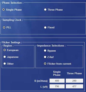
Figure 31 Selecting the Flicker test impedance
Some users have found an elegant work-around, in that they have a separate neutral impedance box, that is placed in line, so the Three Phase programmable impedance and the added neutral impedance box are suitable for 3 phase equipment, even if the EUT is not balanced, i.e. has neutral current flow.
Also, the user may decide to derive the measurement from the EUT current. In this case, the voltage fluctuation is calculated from individual current samples, which are multiplied by the complex reference impedance, and thus provide the voltage changes. Although not as popular as the direct voltage measurement, the current method is in accordance with clause 4.1 of the standard.
17. IEC 61000-3-11 Flicker testing < 75 A (per phase)
The IEC 61000-3-11 standard is similar to the approach for IEC 61000-3-12, in that the user must determine the maximum permissible system impedance that the connection for the equipment is permitted to have.
Therefore, the connection is conditional upon the system impedance, not unlike the conditional connection that is determined by the Rsce for IEC 610003-12 testing. Equipment that fails the unconditional limits of IEC 61000-3-3, may also be tested per IEC 61000-3-11, and the maximum permitted system impedance can be determined.
Because of the higher current levels, the test impedance values are usually as defined for “Z-test” in the standard. The user may opt to have different impedance values, but the values below are recommended.
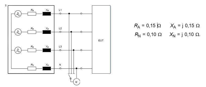
Figure 32 The Z-test for Flicker testing < 75 A-rms
In principle, the measurements per IEC 61000-3-11 are very similar to the IEC 61000-3-3 test, except that the results are “calculated back” to the voltage fluctuations that the EUT would produce IF the test impedance were the Reference Impedance.
The resulting Flicker parameters can then be used to calculate the maximum permissible system impedance.
Evaluation against Zref
When using Z-test instead of Zref, the measured values shall be recalculated using the following formulae:
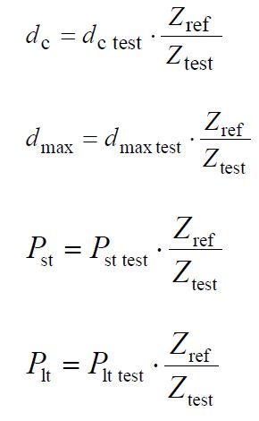
If Z-test equals the values given above in Figure 32, the ratio between Z-ref and Z-test is 1.334. Therefore, the measured Flicker parameters per IEC 61000-3-11, are recalculated i.e. are multiplied by 1.334. These recalculated values are then used to compute the maximum permissible system impedance for the EUT connection.
Calculating the maximum permissible connection impedance
To calculate the maximum permissible system impedance, Zsys, the values of dc, dmax, Pst and Plt according to the above evaluation against Zref. are used in the following formulas.
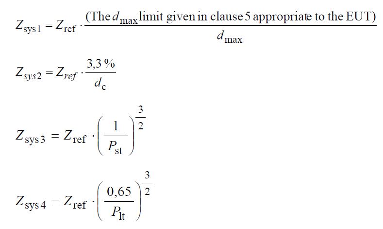
The minimum of the four calculated values of Zsys is the maximum permissible system impedance, Zmax which the manufacturer shall declare in accordance with the requirements per clause 4 of the standard.
For example, if the “dc” measurement per IEC 61000-3-11, using Z-test, equals 2.9 %, the recalculated “dc” will be
1.334 x 2.9 % = 3.87 %. Consequently, the maximum permissible impedance to remain below the 3.3 % limit, equals
3.3 / 3.87 x Zref i.e. maximum 341 m? resistive and j 0.213 ? (679 µH). The 679 µH is generally divided between Line and Neutral per the same ratio in Zref, i.e 0.6 x 679 = 407 µH for the phase and 272 µH for the neutral conductor.
18. A brief overview of the measurement conditions & standards
Harmonics are evaluated using the measurement methods specified in IEC 61000-4-7, and Flicker tests are done with a Flicker meter that meets the requirements per IEC 61000-4-15.
Even though most of the requirements are already mentioned in the previous sections, dealing with IEC 61000-3-2/12 and IEC 61000-3-3/11 there are a few measurement specifications to review. We will first look at IEC 61000-4-7 in conjunction with IEC 61000-3-2/12 and then review IEC 61000-4-15 in conjunction with IEC 61000-3-3/11.
Even though some of the requirements below are specified in either the harmonics emission or Flicker standards, they are discussed here, as they pertain to measurement procedures.
IEC 61000-4-7 requirements & additional IEC 61000-3-2/12 measurement specifications
IEC 61000-3-2 and IEC 761000-3-12 have a reproducibility specification of (1% + 10 mA). Basically, this means that any equipment tested on another harmonics test system, should have results that are within 1 % + 10 mA (for IEC 61000-3-2), with the 1 % taken from the input current. Also, the standard has a repeatability specification, requiring that successive measurements on the same EUT produce results that are within 5 % of each other. This is not a PASS/FAIL criterion, but it is used to make sure the test observation period is long enough. This is especially important for equipment with a fluctuating behavior. If the observation period is too short, large variations can occur. If, however, the EUT easily passes the limits, but the measurements deviate by more than 5 %, the product still passes.
This is particularly applicable for the higher order harmonic limits. For example, the H40 limit in Class-A is 46 mA. A repeatability of 5 % means that successive measurements must be within 2.3 mA from each other, which is difficult but doable. For Class-D and C, however where the limits can be as low as 3 % of say 0.3 A, i.e. 9 mA, the ± 5 % would mean
0.45 mA, which approximates rounding errors.
Fortunately, IEC 61000-3-2 also permits values < 0.6 % of the input current, or < 5 mA to be disregarded.
If successive measurements deviate too much, the user may opt to test for 2.5 minutes under conditions where the highest THC is expected to occur. The table below – from IEC 61000-3-2 and IEC 61000-3-12 provides guidance in selecting the test observation period.
| Type of equipment behavior | Observation period |
| Quasi-stationary | Tobs of sufficient duration to meet the requirements for repeatability ( ± 5 % ) |
| Short cyclic (Tcycle ? 2,5 min) | Tobs ? 10 cycles (reference method) or Tobs of sufficient duration or synchronization to meet the requirements for repeatability ( ± 5 % ) |
| Random | Tobs of sufficient duration to meet the requirements for repeatability ( ± 5 % ) |
| Long cyclic (Tcycle > 2,5 min) | Full equipment program cycle (reference method) or a representative 2,5 min period considered by the manufacturer as the operating period with the highest THC |
| a By 'synchronization' is meant that the total observation period is sufficiently close to including an exact integral number of equipment cycles such that the requirements for repeatability of ± 5 % are met. | |
Figure 33 The Observation period for IEC 61000-3-2/12 testing
IEC 61000-4-7 requires measurement accuracies that are specified in Table-1 of the standard. For all practical purposes, the accuracy requirement for a Class-I instrument (harmonics analyzer) is ± 5 % for voltage and current, and ± 1 % or 1.5 Watt for power. There is an “absolute allowance” for voltage signals that are < 1 % and current signals < 3 % of the nominal measurement range, but these are rarely applicable or used. Note, however, that the reproducibility allowance in IEC 610003-2 (1 % + 10 mA) may exceed and override the ± 5 % in IEC 61000-4-7.
IEC 61000-4-7 Measurement accuracy specification
Table-1 Measurement Accuracy Requirements per IEC 61000-4-7
| Class | Measurement | Conditions | Maximum Error |
| I | Voltage | Um ? 1% Unom Um < 1% Unom |
5% Um 0,05% Um |
| Current | Im ? 3% Inom Im < 3% Inom |
± 5% Im ±0,15% Inom |
|
| Power | PmPm>150W | ± 1,5 W ± 1% of Pm |
|
| II | Voltage | Um ? 3% Unom Um < 3% Unom |
5% Um 0,15% Um |
| Current | Im ? 10 % Inom Im < 10 % Inom |
± 5% Im ± 0,5% Inom |
Figure 34 Table-1 with accuracy requirements from IEC 61000-4-7
Inter-harmonics grouping
Although not mandatory as yet, product testing is recommended to use the measurement method with inter-harmonics evaluation. This requirement is expected to be added as the mandatory test specification in one of the next amendments to IEC 61000-3-2.
Some manufacturers used “spread spectrum” techniques to reduce the integer harmonic levels, i.e. moved some of the energy to the side-bands. Unfortunately, the network distribution transformer and other network equipment heat up just the same, whether the H3 emission is at exactly 150 Hz, or is moved in part to 145 and 155 Hz. Also, resonances are exited virtually the same whether the H5 emission is at exactly 250 Hz, or 245 or 255 Hz. In fact, inter-harmonics have a “better chance” to kick off network resonances.
Co, the IEC committee responded with a harmonic grouping method that basically calculates the rms value of the integer harmonic and its side bands.
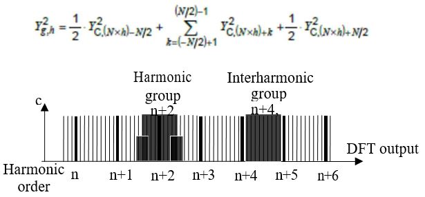
Figure 35 Grouping algorithm from IEC 61000-4-7 and graphically depicted
Note that only intermediate components above 100 Hz (120 Hz) are taken into consideration
In the test configuration screen, the user generally has an option to turn the grouping “on” of “off”. The recommended test is with grouping “on”.
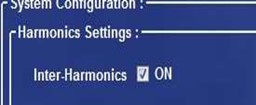
Figure 36 Selecting inter-harmonics
Supply source requirements for IEC 61000-3-2 and IEC 61000-3-12
In order to make sure that the power source does not contribute, nor subtract from the current emissions, IEC 61000-3-2 and IEC 61000-4-7 require that the power source meets the following requirements;
- The test voltage (U) shall be the rated voltage of the In the case of a voltage range, the test voltage shall be 230 V for single phase or 400 V for three-phase supplies.
- The test voltage shall be maintained within ±2,0 % and the frequency within ±0,5 % of the nominal
- In the case of a three-phase supply, the angle between the fundamental voltage on each pair of phases of a three-phase source shall be 120° ± 1,5°.
- The harmonic ratios of the test voltage (U) shall not exceed the following values with the EUT connected as in normal operation:
- 0,9 % for harmonic of order 3;
- 0,4 % for harmonic of order 5;
- 0,3 % for harmonic of order 7;
- 0,2 % for harmonic of order 9;
- 0,2 % for even harmonics of order from 2 to 10;
- 0,1 % for harmonics of order from 11 to
- The peak value of the test voltage shall be within 1,40 times and 1,42 times its r.m.s. value and shall be reached within 87° to 93° after the zero This requirement does not apply when Class A or B equipment is tested.
IEC 61000-3-12 measurement and source requirements
The voltage distortion requirements for the higher power tests per IEC 61000-3-12 are permitted to be higher, see below
- 1,5 % for harmonic of order 5;
- 1,25 % for harmonics of order 3 and 7;
- 0,7 % for harmonic of order 11;
- 0,6 % for harmonics of order 9 and 13;
- 0,4 % for even harmonics of order 2 to 10;
- 0,3 % for harmonics of order 12 and 14 to 40;
The power source output impedance must be very low, so that the Rsce is equal to or higher than the anticipated minimum Rsce value (Rsce min). This would allow the insertion of inductors to reduce harmonics.
In either case, the test system must monitor the voltage stability, frequency, and distortion level. There are a few more details like the method to assess the phase angle of the 5th harmonic. This issue is part of an amendment (or a new edition 3) and it will be addressed when applicable.
Also, IEC 61000-4-7 specifies measurement methods in the range from 2 – 9 kHz. This will be addressed when the applicable standard with limits in the range from 2-9 kHz is published.
IEC 61000-4-15 requirements & additional IEC 61000-3-3/11 measurement specifications
IEC 61000-3-3 and IEC 61000-3-11 require that the overall measurement accuracy is within ± 8 %. This includes the Flicker meter as well as the Reference Impedance Z-ref) and/or Z-test.
For the Flickermeter itself, the specification is to have an accuracy specification of ± 5 %, with a maximum permitted deviation of Pst to be ± 5 % or ± 0.05 whichever is larger. The Flickermeter should meet the normalized response curve specification as illustrated below ( for an instantaneous Psti of 1.00).
| Hz |
Voltage fluctuation DU/U % |
Hz |
Voltage fluctuation DU/U % |
||
| 230-V lamp 50 Hz system | 230-V lamp 60 Hz system | 230-V lamp 50 Hz system | 230-V lamp 60 Hz system | ||
| 0,.5 | 0,509 | 0,510 | 11,5 | 0,233 | 0,233 |
| 1,0 | 0,467 | 0,468 | 12,0 | 0,245 | 0,244 |
| 1,5 | 0,429 | 0,429 | 13,0 | 0,272 | 0,275 |
| 2,0 | 0,398 | 0,399 | 14,0 | 0,308 | 0,306 |
| 2,5 | 0,370 | 0,371 | 15,0 | 0,341 | 0,338 |
| 3,0 | 0,352 | 0,351 | 16,0 | 0,376 | 0,376 |
| 3,5 | 0,342 | 0,342 | 17,0 | 0,411 | 0,420 |
| 4,0 | 0,332 | 0,331 | 18,0 | 0,446 | 0,457 |
| 4,5 | 0,312 | 0,313 | 19,0 | 0,497 | 0,498 |
| 5,0 | 0,291 | 0,291 | 20,0 | 0,553 | 0,537 |
| 5,5 | 0,268 | 0,269 | 21,0 | 0,585 | 0,584 |
| 6,0 | 0,248 | 0,249 | 21,5 | 0,592 | 0,600 |
| 6,5 | 0,231 | 0,231 | 22,0 | 0,612 | 0,611 |
| 7,0 | 0,216 | 0,217 | 23,0 | 0,680 | 0,678 |
| 7,5 | 0,207 | 0,206 | 24,0 | 0,743 | 0,753 |
| 8,0 | 0,199 | 0,200 | 25,0 | 0,764 | 0,778 |
| 8,8 | 0,196 | 0,196 | 25,5 | 0,806 | 0,768 |
| 9,5 | 0,199 | 0,199 | 28,0 | 0,915 | 0,962 |
| 10,0 | 0,203 | 0,203 | 30,5 | 0,847 | 1,105 |
| 10,5 | 0,212 | 0,212 | 33 1/3 | 1,671 | 1,258 |
| 11,0 | 0,222 | 0,222 | 37,0 | 0,975 | |
| 40,0 | 2,327 | ||||
Figure 37 Flickermeter response curve specification
The above table (Figure 37) is intended for type testing or qualification of the Flickermeter. For annual calibration, such as required for accreditation renewal, a more limited set of test points is specified in Table-5 of the IEC 61000-4-15 standard. Also, there are several types of Flickermeters defined. Class-F1 meters to be used to measure on public supply networks, must have a larger measurement range, and be able to process just about every voltage signal, whether it is distorted, has frequency changes, or whether phase-jumps occur on the network. For testing to IEC 61000- 3-3/11, the Class-F2 Flickermeter is suitable. Test per IEC 61000-3-3/11 are normally in a controlled environment, and voltage steps > 7 % result in a failed test.
The requirements, as given in Table-5 of IEC 61000-4-15 for annual testing are illustrated below. If a Flickermeter meets the 7 crucial checkpoints, it can reasonably be expected that the meter complies with the test table of Figure 37.
Furthermore, if the test results are within ± 8 %, it can be reasonably expected that the system, consisting of the meter, the Reference Impedance, and the system integration meets the requirements of IEC 61000-3-3.
|
Rectangular changes per minute CPM |
Voltage fluctuation % |
|||
| 120 lamp 50 Hz system | 120 V lamp 60 Hz system | 230 V lamp 50 Hz system | 230 V lamp 60 Hz system | |
| 1 | 3,178 | 3,181 | 2,715 | 2,719 |
| 2 | 2,561 | 2,564 | 2,191 | 2,194 |
| 7 | 1,694 | 1,694 | 1,450 | 1,450 |
| 39 | 1,045 | 1,040 | 0,894 | 0,895 |
| 110 | 0,844 | 0,844 | 0,722 | 0,723 |
| 1 620 | 0,545 | 0,548 | 0,407 | 0,409 |
| 4 000 | 3,426 | Test not required | 2,343 | Test not required |
| 4 800 | Test not required | 4,837 | Test not required | 3,263 |
| NOTE 1 620 rectangular changes per minute correspond to a rectangular square wave modulation frequency of 13,5 Hz.NOTE 2 For tests according to this table, the first voltage change is applied within 5 s after the Pst evaluation is started. Flickermeters having a pre-test time to charge the filters, should indicate when the Pst evaluation starts, so that the testing authority can determine when to start the rectangular modulation pattern. | ||||
Figure 38 Flickermeter test & calibration table for routine testing
Although this is not specified, it follows that if IEC 61000-3-3 permits ± 8 %, and IEC 61000-4-15 permits ± 5 %, this leaves ± 3 % for the combination of Reference Impedance (or Z-test), the system integration plus the power source impedance.
Most Flickermeters have a response that is within about 1-2 %, so that gives a bit more headroom for the impedance. After all, it’s not easy to have a Reference Impedance that is within ± 12 m? from ideal (± 7.5 m? for Z-test).
Generally, the above tests per Figure 38 can be done by applying a current that is turned “on” and “off” per the frequencies in CPM in the first column. For example, 7 changes per minute means, the current is turned “on” for 8.57 seconds and then turned “off” for 8.57 seconds, in a repetitive pattern.
Alternatively, one can test just the Flickermeter by applying a modulated voltage, but that does nothing for the Z-ref (or Z- test) and the power source or system wiring.
Basically, all the requirements for IEC 61000-3-3 also apply to IEC 61000-3-11.
IEC 61000-4-15 also provides test tables for phase jumps, voltage fluctuations with a varying duty cycle, and tests on distorted voltages (with side-bands). As this tutorial deals with testing per IEC 61000-3-3/11, only the relevant parts of IEC 61000-4-15 are explained.
19. An overview of power line immunity problems
The public supply voltage is not ideal, i.e. it is not a clean sinewave that is perfectly stable at the nominal voltage. Rather, it is usually distorted, and is subject to voltage fluctuations and interrupts. In addition to “unwanted” disturbances, there are also control signals (called ripple control) that the utilities inject/superimpose into the network, to control network equipment. For example, the Wattmeter may be switched to night-tariff by a control signal, or a transformer tap may be switched to a high or lower voltage. As more customers start using electrical appliances in the morning, the utility can switch to a different tap to increase the voltage slightly (to compensate for higher losses due to increased loads)
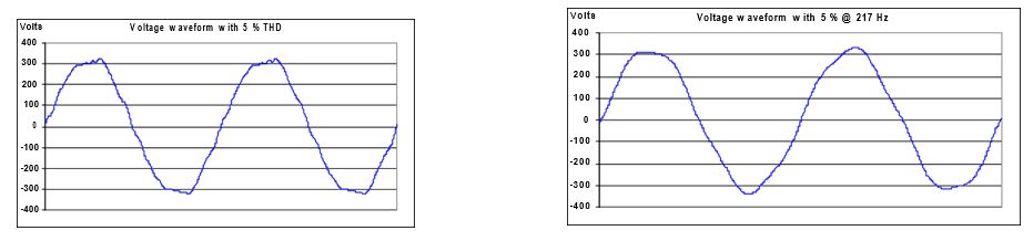
Figure 39 Typical flat top waveform in the home Typical waveform with 217 Hz control signal superimposed
| Annual voltage disturbances by depth and duration in Western Europe | |||||
| Remaining voltage | Duration of disturbance | ||||
| during disturbance | 10 - 100 ms | 0.1 - 0.5 s | 0.5 - 1 s | 1 - 3 s | Total/yr |
| 161 - 230 Volt | 61 | 66 | 12 | 6 | 145 |
| 92 - 161 Volt | 8 | 36 | 4 | 1 | 49 |
| 0 - 92 Volt | 2 | 17 | 3 | 2 | 24 |
| Zero volt | 0 | 12 | 24 | 5 | 41 |
Figure 40 Dips and interrupts reported by Eurelectric in the 1990’s
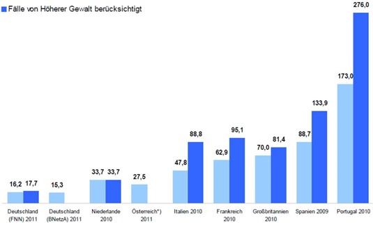
Figure 41 Unavailability of electrical supply in minutes/year European countries (2012 reported by FNN / VDE ).
Average, including interruptions, is about 90 minutes/Yr.
As solar and wind-energy increase, there is some concern that the power quality will deteriorate, although serious dips and interrupts should not be affected that much.
In either case, even in “super stable” networks in Germany, The Netherlands and Austria, dips and interrupts are common, and amount to a loss of power for a total of about 20 minutes per year. In The Netherlands, a total of 19,366 interruptions took place, with an average 122 customers losing power, with most interruptions originating from the medium voltage (MV) network. Network equipment defects and aging represented about half the disturbances, with construction activities being the 3rd most common cause with about 25 % of all MV cases. At the low voltage (LV) level,
i.e. the household voltage, construction work (damaging power lines) represented about 27 % of all interrupts, with equipment aging and defects add another 23 %.
Note that the unavailability in Italy and other European countries, is much higher, i.e. the number of interruptions is substantially higher. The table in Figure 40 shows the distribution in time and voltage level for the dips and interrupts in the 1990’s.
A short circuit in the home at one outlet, causes the voltage at other outlets to briefly go to near zero (until the affected circuit breaker trips). Even neighboring homes can “see” all or part of the dip. If a big electric motor is started, or other major load changes occur, it will affect the voltage in that area, and cause it to drop for a given percentage.
The voltage distortion in the network see Figure 39 and Figure 1 in the Background section, can be significant. Ripple control signals can be as high as 8 -9 % of the nominal voltage.
It will be clear by now, that electrical equipment must have either full immunity for these disturbances, or have a controlled way to shut down and re-start after the disturbance is gone.
IEC 61000-4-11 Testing
The IEC 61000-4-11 standard specifies methods to verify that electrical products can handle dips and interrupts. Recommended test levels are given in Table-1 of the standard. Most consumer electrical products fall in Class-2, with Class-3 and Class-X reserved for industrial equipment and special equipment.
| Classa | Test level and durations for voltage dips (ts) (50 Hz/60 Hz) | ||||
| Class 1 | Case-by-case according to the equipment requirements | ||||
| Class 2 | 0 % during ½ cycle | 0 % during 1 cycle | 70 % during 25/30c cycles | ||
| Class 3 | 0 % during ½ cycle | 0 % during 1 cycle | 40 % during 10/12c cycles | 70 % during25/30c cycles | 80 % during 250/300c cycles |
| Class Xb | X | X | X | X | X |
|
a Classes as per IEC 61000-2-4; see Annex B. b To be defined by product committee. For equipment connected directly or indirectly to the public network, the levels must not be less severe than Class 2. c "25/30 cycles" means "25 cycles for 50 Hz test" and "30 cycles for 60 Hz test". |
|||||
Figure 42 recommended dips/inetrrupt test levels and duration per IEC 61000-4-11
Some of the Table-1 dips-interrupt tests are illustrated below
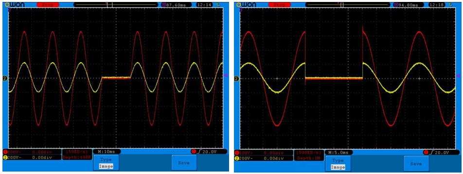
Figure 43 1 cycle drop-out starting at “0” (left) and starting at 90 degrees (right)
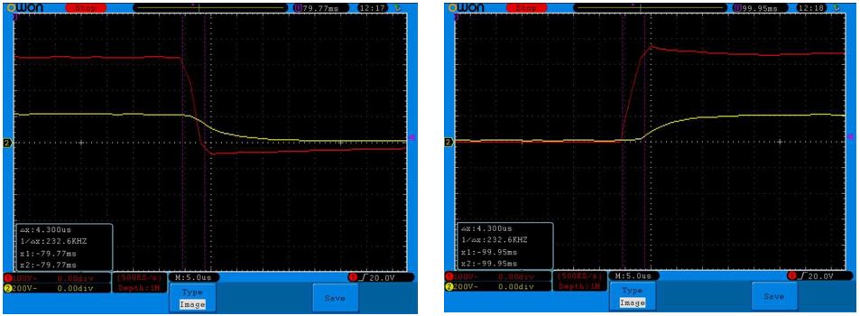
Figure 44 Fall time and rise time @ 90 degrees in the order of 3 – 4 µS, for the 1 cycle starting @ 90 deg
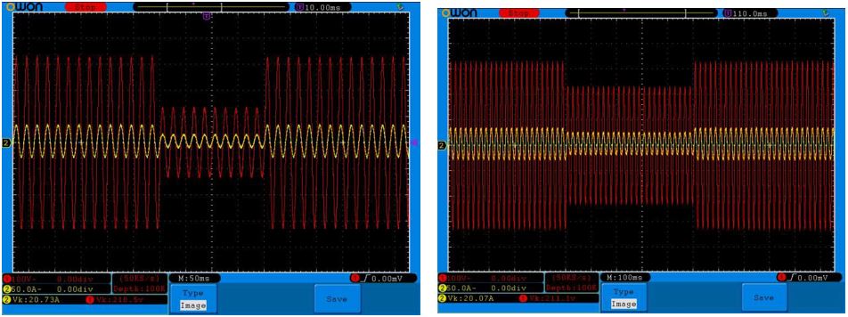
Figure 45 A voltage dip to 40 % remaining for 10 cycles, and 70 % remaining for 25 cycles (per Table-1)
The standard also defines the requirement for voltage interruptions that start at 90 or 270 degrees. The test generator has to be able to make the transition from full voltage to “zero” and back up within 1 – 5 µS with a 100 ? resistive load.
Note that there are several acceptable criteria to “PASS” or FAIL the test per IEC 610004-11.
Acceptable criteria for passing IEC 61000-4-11
The EUT shall have;
- normal performance within limits specified by the manufacturer, requestor or purchaser
- temporary loss of function or degradation of performance which ceases after the disturbance ceases, and from which the equipment under test recovers its normal performance, without operator
- temporary loss of function or degradation of performance, the correction of which requires operator intervention (per the manufacturer specification).
Equipment fails the test if;
- there is loss of function or degradation of performance which is not recoverable, because of damage to hardware or software, or loss of
Switch method to achieve fast rise/fall times
The standard illustrates several methods to achieve the 1 – 5 µS rise/fall times. This ONLY applies to a test with a 100 ? resistive load. There are no requirements for rise/fall time when doing actual product testing, as the 1 – 5 µS is virtually impossible to guarantee, because the load type has a big influence.
Note that even when using the approach shown in Figure 46, the combined supply and transformer inductance cannot exceed 200 µH. In fact, for a system that has an impedance that is typical of the European network, the rise/fall time will be in the order of 20 – 25 µS. So, one generally needs to use a programmable power source, which typically has 80 - 100 µH inductance in the output. That leaves about 100 µS for the transformer.
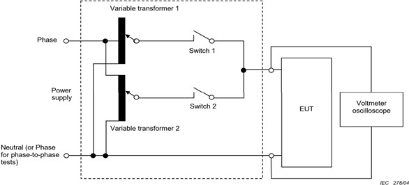
Figure 46 Method to achieve 1 – 5 µS rise/fall times for a single phase setup
3 Phase test patterns
IEC 61000-4-11 also defines some test patterns for 3 phase equipment testing, where the voltage dip can be generated either by changing the phase angle of phases, or by reducing the amplitude of one of the phases with respect to neutral. The method where one phase voltage is reduced is depicted below.
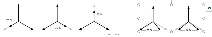
Figure 47 Methods to have 1 phase dip to 70 %, or have two phases with reduced voltage
Figure 48 2 phases A & C dip to 70 %, and Phase B remains stable
IEC 61000-4-11 Test Generator requirements
Apart from the rise-fall specification, the test generator must be capable to;
- Deliver 500 A inrush current – or at least 4 x the inrush current demand of the EUT
- Maintain the programmed nominal voltage or the dip-to voltage within 5 %
- Support the rms current demand of the EUT or be rated for 16 A
- Have the capability to start dips/interrupts at any angle from 0 – 360 degrees with ± 10 deg accuracy
IEC 61000-4-13 harmonic and inter-harmonic immunity testing
As explained in Section 20 (Overview) it is common to have harmonic and/or inter-harmonic distortion on the public supply network. In addition to the unwanted distortion, caused by non-linear loads, there are also the ripple control signals, which are deliberately super-imposed on the voltage by utilties (to control network elements).
IEC 61000-4-13 defines a series of tests with varying distortion levels at harmonic and interharmonic frequencies. The user can decide to run all or part of the tests.
For example, one can select the harmonic and interharmonic, or the so-called flat top and over-swing patterns
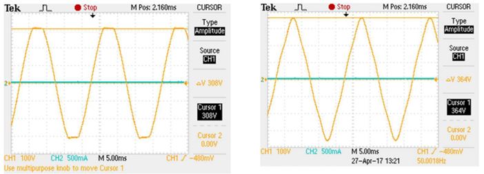
Figure 49 The Class-2 Flat-top and Over-swing waveform per IEC 61000-4-13
Note that the “flat-top” is a representation of the distortion cause by non-linear single phase electrical products, like PC’s, laptop supplies, phone and tablet chargers etc. The over-swing waveform represents the voltage distortion pattern that is often found in industrial areas where 3 phase equipment is operated. IEC 61000-4-13 defines the levels of harmonics and the required waveform for these flat-top and over-swing patterns in Tables-7 and 8 of IEC 61000-4-13.
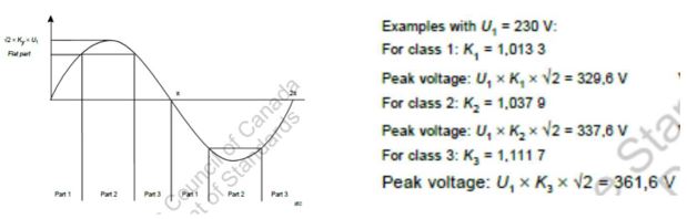
Figure 50 The Flat-top parameters for Class-1, 2, and 3 in IEC 61000-4-13
The standard also defines levels for odd, and for even harmonics, as well as for inter-harmonics testing. In addition, there is the so-called Meister Curve with levels per frequency range. The Meister Curve simulates the ripple control voltages that a utility may super-impose on the network, and it basically covers also the integer harmonics and inter-harmonics. Figure 51 shows the spectrum for a Meister Curve test, starting at
16.5 Hz @ 3 %, 9 % from 100 – 500 Hz, and a decreasing level from 500 – 2000 Hz. The modulation percentage for that range is equal to 4500 / f, where “f” is the frequency. So, at 2000 Hz, the level must be ideally 4500/2000 = 2.25 %
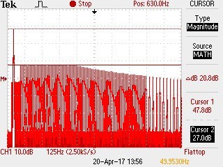
Figure 51 The Meister Curve sweep test 16.5 – 2000 Hz
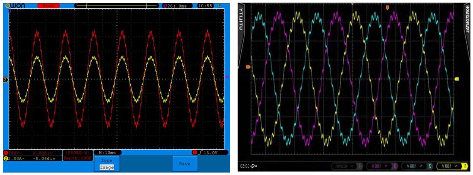
Figure 52 Single phase and 3 phase modulation patterns as part of the Meister Curve
IEC 61000-4-13 Test Generator requirements
- The test generator for IEC 61000-4-13 must keep the voltage stable to within ± 2 % and keep the frequency to within 5 % during the test.
- The nominal test voltage Un must be within ± 5 % (or within 1 % Un for the harmonics
- For 3 phase testing the phases must be 120 degrees ± 5 degree
- The phase angle of harmonics 2 – 9 must be programmable from 0 – 180 degrees
IEC 61000-4-14 Voltage Fluctuation testing
The IEC 61000-4-14 standard establishes a common test method for products, which must be evaluated for their susceptibility to disturbances from voltage fluctuations at levels up to ± 10% of the nominal system voltage. Generally it is unusual for a product to be susceptible to such disturbances and is therefore not a generic requirements, but specified only in product family standards where known problems exist.
Much like IEC 61000-4-11, the IEC 61000-4-14 standard also defines recommends test levels by product class.
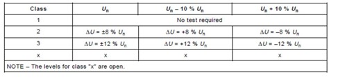 Figure 53 Recommended test levels by Class per IEC 61000-4-14
Equipment Classifications per IEC 61000-4-14
Annex A of the standard defines the electromagnetic environments for the different test classes.
- Class 1 Applies to protected supplies with compatibility levels lower than public supply It includes to the use of equipment, which is very sensitive to disturbances in the power supply, for instance the instrumentation of technological laboratories, some computers etc. This equipment is normally supplied by protected supplies such as uninterruptible power supplies.
- Class 2 Applies to points of common coupling (PCCs for consumer systems) and in-plant points of common coupling (IPCs) in industrial environments in The compatibility levels in this class are identical to those used for public networks.
- Class 3 Applies only to IPCs in industrial environments. It has higher compatibility levels than those of class 2 for some disturbance phenomena. This class should be considered when any of the following conditions are met:
- a major part of the load is fed through converters
- welding machines are present
- large motors are frequently started
- loads vary rapidly
Class X specifications are to be agreed upon by the manufacturer and user, while testing for Class-1
Typical test sequence
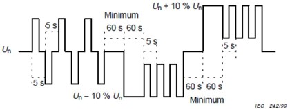
Figure 54 shows a typical test sequence, with voltage variations of 8 % and 10 % and varying time between fluctuations.
The EUT is normally tested with 3 sequences of each combination of supply voltage and test level. So, the test starts with U-nominal, then a test starting with N-no – 10 % and last is a test starting with U-nom + 10 %. These 3 test sequences are depicted in Figure 55 below..
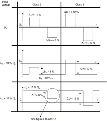
Figure 55 Single phase and 3 phase modulation pattern per the Meister Curve
IEC 61000-4-14 Test Generator requirements
The generator requirements for IEC 61000-4-14 testing are very similar to those for IEC 61000-4-11.
- The test generator for IEC 61000-4-14 must keep the voltage stable to within ± 1
- The nominal test voltage Un can be within ± 25 % from U-nominal
- Voltage changes from one level to another must be within 1 ms
- Frequency accuracy must be within ± 2.5 % of 50 Hz or 60 Hz
- For 3 phase testing the phases must be 120 degrees ± 5 degree
IEC 61000-4-27 Unbalance in 3 phase systems testing
The objective of IEC 61000-4-27 is to test equipment for immunity to unbalance of 3 phase power supply systems. At the low voltage (100 – 240 V / phase) public supply, many products are connected to just one phase. Also, in large buildings with 3 phase coming in, separate branches feed sections of the building. A fault can occur at the low voltage level in one phase, which momentarily causes an unbalance condition. At the medium voltage level, single phase arc furnaces can cause one phase to be lower i.e. and unbalance condition.
As with the foregoing standards, IEC 61000-4-27 defines several test classes.
- Class 1 Applies to protected supplies with compatibility levels lower than public supply It includes to the use of equipment, which is very sensitive to disturbances in the power supply, for instance the instrumentation of technological laboratories, some computers etc. This equipment is normally supplied by protected supplies such as uninterruptible power supplies.
- Class 2 Applies to points of common coupling (PCCs for consumer systems) and in-plant points of common coupling (IPCs) in industrial environments in The compatibility levels in this class are identical to those used for public networks.
- Class 3 Applies only to IPCs in industrial environments. It has higher compatibility levels than those of class 2 for some disturbance phenomena. This class should be considered when any of the following conditions are met:
- a major part of the load is fed through converters
- welding machines are present
- large motors are frequently started
- loads vary rapidly
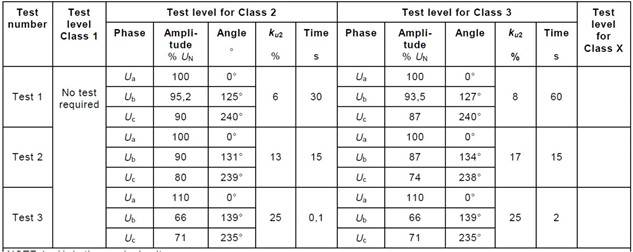
Figure 56 Recommended tests per IEC 61000-4-27
There are several test patterns specified in IEC 61000-4-27, with voltage variations starting at “0” degrees or with different levels and phase angle change combinations. As with the foregoing test standards, Class-2 is typically the most important test. Class=3 equipment is often operated in so-called private networks. Figure 57 below depicts a voltage variation where one of the phases
IEC 61000-4-27 Test Generator requirements
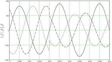
Figure 57 Recommended tests per IEC 61000-4-27
Example of a change that starts at the zero crossing of the undisturbed phase.
The generator requirements for IEC 61000-4-17 testing are very similar to those for IEC 61000-4-14.
- The test generator for IEC 61000-4-27 must keep the voltage stable to within ± 2 %
- The nominal test voltage Un can be within ± 50 % from U-nominal
- Voltage changes from one level to another must be within 1 – 5 µS
- Frequency accuracy must be within ± 0.5 % of 50 Hz or 60 Hz
- Voltage distortion must be less than 3 %
- The generator must be able to apply a + or – phase shift of 30 deg to either
IEC 61000-4-28 Frequency variations testing
In general, the frequency of public supply networks is well regulated and any variations tend to be small. However, in private or isolated networks such as islands and perhaps in developing countries, the frequency variations can be much greater. IEC 61000-4-28 establishes a common test method for products, which must be evaluated for their susceptibility to these variations. This test is only required by specific product family standards where potential problems exist.
Equipment Classifications per IEC 61000-4-28
The equipment classification is very similar to those specified in IEC 61000-4-14 and IEC 61000-47n Annex B of the standard, the EUT operating environment classifications are defined based on IEC 61000-2-4. The classifications are as follows:
- Class 1 Applies to protected supplies with compatibility levels lower than public supply It includes to the use of equipment, which is very sensitive to disturbances in the power supply, for instance the instrumentation of technological laboratories, some computers etc. This equipment is normally supplied by protected supplies such as uninterruptible power supplies.
- Class 2 Applies to points of common coupling (PCCs for consumer systems) and in-plant points of common coupling (IPCs) in industrial environments in The compatibility levels in this class are identical to those used for public networks.
- Class 3 Applies only to IPCs in industrial environments. It has higher compatibility levels than those of class 2 for some disturbance phenomena. This class should be considered when any of the following conditions are met:
- a major part of the load is fed through converters
- welding machines are present
- large motors are frequently started
- loads vary rapidly
Frequency variation test levels;
| Level 1 | Class 1 | No test required |
| Level 2 | ± 3 % of nominal frequency | |
| Level 3 | Class 3 used in interconnected networks | + 4 % and - 6 % of nominal frequency |
| Level 4 | Class 3 used in private networks | ± 15 % of nominal frequency |
| Level X | Product class specific | Open but is required to > level 2 |
Generally, the frequency variations are relatively slow, and can be followed with a fast frequency meter. One can, however also verify the frequency variation with a digital storage oscilloscope, as shown in Figure 58. The starting frequency is 50 Hz ( 80 ms for 4 cycles ). As the frequency is lowered, the 4 cycles need 8 ms more i.e. 88 ms, indicating a frequency of 45.5 Hz. The scope picture also shows the frequencies between 50 Hz and 45.5 Hz.
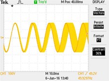
Figure 58 Recording frequency variations with a digital oscilloscope
The test sequences are to change the frequency (the 3 % etc.) is 10 seconds from nominal to the desired frequency, and then hold the modified frequency for 120 seconds. This is easily verified with a frequency meter and an oscilloscope.
IEC 61000-4-28 Test Generator requirements
The generator requirements for IEC 61000-4-28 testing are not unlike the requirement for IEC 61000-4-14.
- The test generator for IEC 61000-4-28 must keep the voltage stable to within ± 2 %
- Frequency changes from one level to another must be programmable
- Nominal frequency accuracy must be within ± 0.5 % of 50 Hz or 60 Hz
- Voltage distortion must be less than 3 %
20. IEC 61000-4-17 & IEC 61000-4-29 disturbances on DC power lines
DC supplies are generally private network, so testing per IEC 61000-4-17 or IEC 61000-4-39 does not really fit in the powerline immunity test requirements. Given the use of DC networks in sensitive areas, and the growing popularity of DC networks in data centers, we will review both standards in this tutorial.
The object IEC 61000-4-17 is to establish a common and reproducible basis for testing equipment that is used in a laboratory, and electrical and electronic equipment that is subjected to ripple voltages such as those generated by rectifier systems and/or auxiliary service battery chargers overlaying on DC. power supply sources.
IEC 61000-4-29 specifies test methods for dips and interrupts on the DC supply, similar to the IEC 61000-4-11 standard for public supply (AC 50/60 Hz) networks. The object of this standard is to establish a common and reproducible basis for testing electrical and electronic equipment that may be subjected to voltage dips, short interruptions or voltage variations on DC input power ports.
IEC 61000-4-17 Ripple on DC supply (input ports of electrical equipment)
When AC is rectified, the resulting DC voltage may have ripple on it, the frequency of which depends on whether it is a single phase or multi-phase rectification system. This applies to small systems, like battery chargers as well as bigger systems. For example, the ripple frequency might be 2 x line ( 100 / 120 Hz ) or 2 x 3 phase line ( 300 Hz) on a 48 VDC supply, as shown in Figure 59. The ripple might also be sinusoidal, such as the 50 Hz sinusoidal modulation as shown in Figure 60.
To generate signals that represent ripple on DC, the signal generator must have arbitrary waveform capability.
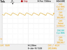
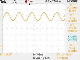
Figure 59 Ripple frequency of 300 Hz Figure 60 Sinusoidal ripple frequency of 300 Hz
The standard recommends test levels as shown in the table in Figure 61. Note that these levels are peak-to-peak voltages
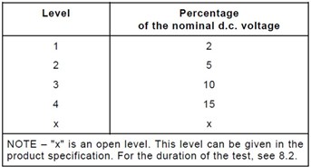
Figure 61 Ripple frequency of 300 Hz
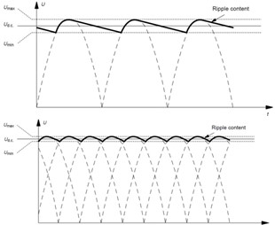
Figure 62 Ripple frequency of 2 x line frequency from a single phase bridge rectifier, Figure 63 Ripple frequency of a 3 phase system
IEC 61000-4-17 Test Generator requirements
The generator requirements for IEC 61000-4-17 testing are as follows
- The test generator for IEC 61000-4-17 must be able to generate up to 360 VDC
- Voltage changes with full load < 5 % ( up to 25 Amp )
- Output voltage accuracy must be within ± 10 %
- Ripple frequency accuracy must be ± 1 %
A generator with lower voltage and/or current specifications is permitted, provided the generator can deliver at least 20 % more than the EUT requires.
In order to pass the test, the EUT shall have;
- normal performance within limits specified by the manufacturer, requestor or purchaser
- temporary loss of function or degradation of performance which ceases after the disturbance ceases, and from which the equipment under test recovers its normal performance, without operator
- temporary loss of function or degradation of performance, the correction of which requires operator intervention (per the manufacturer specification).
Equipment fails the test if;
- there is loss of function or degradation of performance which is not recoverable, because of damage to hardware or software, or loss of
IEC 61000-4-29 Dips and interrupts on DC supply networks
As explained earlier, IEC 61000-4-29 specifies test methods for dips and interrupts on the DC supply, similar to the IEC 61000-4-11 standard for public supply (AC 50/60 Hz) networks. The recommended test levels are given in the tables of Figure 65 – 66 -67. The standard differentiates between dips (Fig. 66) short interruptions (Figure 67) and voltage variations (Figure 68). It will be obvious that short interruptions of 1, 3,10, or 30 ms, require a very fast (expensive) test generator, or a fast switch in conjunction with 2 programmable DC power sources. The latter approach is illustrated in Figure 64. Note that for the “high impedance” test condition, both switches have to be open.
An example of a 10 ms short interrupt is shows in Figure 68.
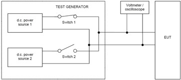
Figure 64 Fast switches to achieve very short interrupt times in the milli-second range, see Figure 65 A,B,C.
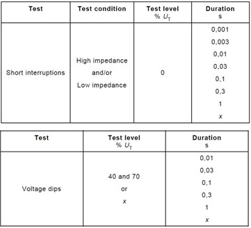
Figure 65 Fast switches to achieve very short, Figure 66 Fast switches to achieve very short
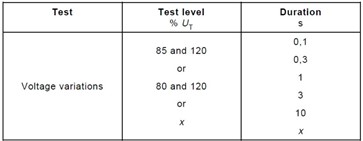
Figure 67 Fast switches to achieve very short
IEC 61000-4-29 Test Generator requirements
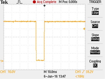
Figure 68 Example of a 10 ms interrupt of a 48 VDC supply
The generator requirements for IEC 61000-4-17 testing are as follows
- The test generator for IEC 61000-4-17 must be able to generate up to 360 VDC
- Capability to produce dips/interrupts as given Figures 65 – 66 –
- Voltage changes with full load < 5 % ( up to 25 Amp )
- Output voltage accuracy must be within ± 5 %
- Ripple content on DC voltage < 1 %
- Switching time from one level to the next between 1 – 50 µS
A generator with lower voltage and/or current specifications is permitted, provided the generator can deliver at least 20 % more than the EUT requires, and maintains the requirements for switching speed, ripple content, and accuracy.
In order to pass the test, the EUT shall have;
- normal performance within limits specified by the manufacturer, requestor or purchaser
- temporary loss of function or degradation of performance which ceases after the disturbance ceases, and from which the equipment under test recovers its normal performance, without operator
- temporary loss of function or degradation of performance, the correction of which requires operator intervention (per the manufacturer specification).
Equipment fails the test if;
- there is loss of function or degradation of performance which is not recoverable, because of damage to hardware or software, or loss of
21. Calibration of test systems
IEC TR 61000-4-37 for harmonics and IEC TR 61000-4-38 for Flicker provide guidance for calibrating and verifying test systems. The test setup is as shown in Figure 69 below. The same setup can be used to test for IEC 61000-4-11, IEC 61000-4-13, IEC 61000-4-28, and IEC 61000-4-29, provided one of the linear loads is a 100 ? resistor.
An oscilloscope will generally be required in parallel to the Reference DVM in the figure. The calibration load has various load levels that can be turned on/off with precise timing characteristics .is capable to generate test patterns as shown for a Class-A PASS test in Figure 70. The current waveform (blue) starts at 45 degrees and ends at 135 degrees. The ideal harmonic content of this waveform is easily computed, and this can be compared against the measured values that the system produces.
Flicker test patterns, where the load is turned “on/off” at precise time intervals are possible as well. This is illustrated in Figure 70, for a 8.77 Hz modulation pattern. As can be seen, the current (yellow) is turned on/off with the desired timing. Knowing the load (or measuring the current when “on”) allows an exact computation of the expected Flicker levels, of both Pst as well as the directly measured parameters.
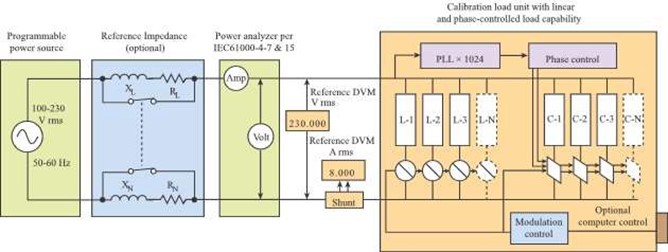
Figure 69 Test setup for calibration and verification of IEC test systems.
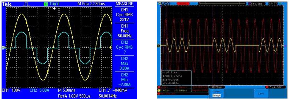
Figure 70 A Class-A Pass waveform and Flicker pattern produced by the calibration load
22. Summary and recommendations
Product testing to IEC standards for power line emissions and immunity is a diverse field, and requires good knowledge of programmable power source and test generators. System calibration and verification requires detailed knowledge of the IEC standards and Technical reports.
The reader may just be interested in some of the standards discussed, although all standards may apply for testing laboratories. Some standards are “more popular” than others, as several of the horizontal standards are mandatory requirements for electrical products, while others only apply if a product standard, a company, or a government agency requires the test.
This tutorial is what the word implies. It is not an exhaustive review of the standards and test methods. It is, however, an excellent entry point to the topic of power line emissions and immunity. For more details the reader is encouraged to obtain the relevant documents from the IEC web site;
https://www.iec.ch/
Additional information – especially on harmonics and Flicker, and system calibration, is also available from CNS Inc. at;
Questions or comments may be directed to Mathieu van den Bergh at