CDG 7000-75-10 Magnetic & Conducted Immunity, 10 kHz - 250MHz

The CDG 7000 is a new test generator for all standards on immunity to conducted disturbances induced by high-frequency fields - including BCI tests (ISO 11452-4). One of the very few combined IEC 61000-4-6 test systems that contain the RF signal generator, an RF power amplifier, a 3-channel RF voltmeter, and a directional coupler at a very affordable price. IEC 60601-1-2 calling out IEC 61000-4-39 magnetic immunity for close proximity testing requirements can also now be met with the 10 kHz unit. 

IEC 60601-1-2 ED. 4.1 / IEC 61000-4-39

SPECIFICATIONS


CDG 7000-75-10 - Magnetic and Conducted Immunity, Induced HF, 9 kHz - 250 MHz

IEC 60601-1-2 ED. 4.1 / IEC 61000-4-39

New requirement, immunity to proximity magnetic fields based on IEC 61000-4-39

  • IEC / EN 61000-4-6 
  • IEC 61326-3-2
  • NAMUR
  • MIL-STD-461 / DO-160
  • IEC 60601-1-2 Ed.4.1 to IEC 61000-4-39 (Close Proximity Magnetic immunity) see below
  • Please check out CDG 7000 page for the general specification of the generator


The IEC 60601-1-2 standard is the international standard for testing medical equipment to EMC. The latest update adds a new test as more transmitter products are present in homes, offices (locations where medical equipment may be used), and hospitals. Three frequencies that are in use are: 30 kHz, 134.2 kHz, and 13.56 MHz. The standard IEC 61000-4-39 for testing fields in close proximity is referenced for this testing. With our IEC 60601-1-2 setup these test fields can be produced.

 Requirements: IEC 60601-1-2
Test Frequency 30 kHz 134,2 kHz 13,56 MHz
Modulation Continuous-wave Pulse modulation 2,1 kHz Pulse modulation 100 kHz
Immunity Test Level (A/m) 8 65 7,5


 Requirements: IEC 61000-4-39 
Frequency range 9 kHz to 150 kHz 150 kHz to 26 MHz
Level Test field strength (A/m) Test field strength (A/m)
1 1 0,1
2 3 0,3
3 10 1
4 30 3
X Special Special
Modulation Amplitude modulation Pulse modulation
Frequency 1 kHz 2 Hz, 1 kHz
Parameter 80% 50% duty cycle


The magnetic loops are specified in IEC 61000-4-39 and are readily available. However, producing a field through the loops might not be straightforward. The loop impedance changes over its frequency range and the amplifier being used will not match this impedance. The result would be a much higher power requirement. In this case, we are not covering a frequency range but individual frequency points. This allows a matching network to be created to match the loop to the amplifier's impedance.
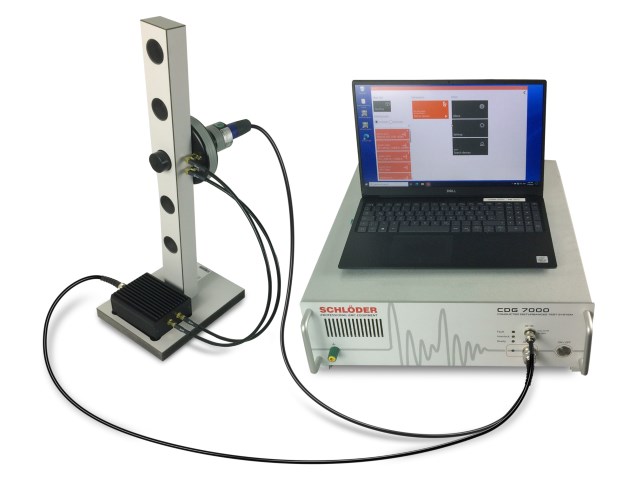
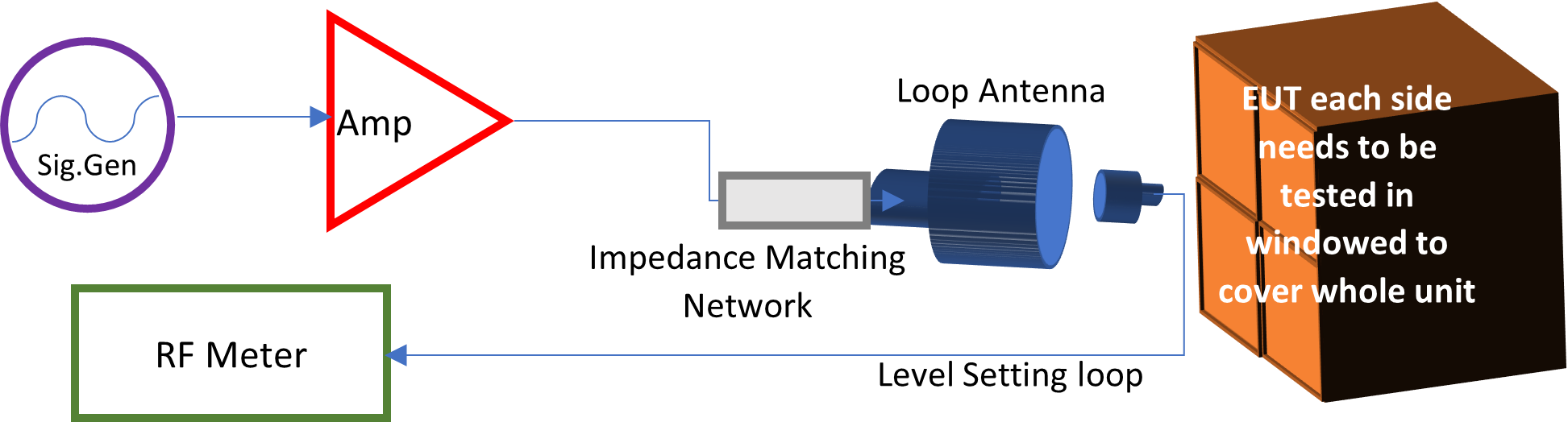
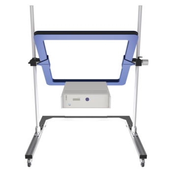
 

Basic Setup

Schlöder has created a system to match this requirement. The system is computer-controlled to set the field level and perform testing with report generation.


In combination with the CDG 7000-75-10 (PA) and a complete set for the corresponding frequency range, international standards (IEC 60601-1-2 ED. 4.1 / IEC 61000-4-39) for testing medical devices for electromagnetic compatibility can be carried out. These complete sets include a radiating loop, a loop sensor, the matching network for the impedance, and a corresponding stand for the loops.


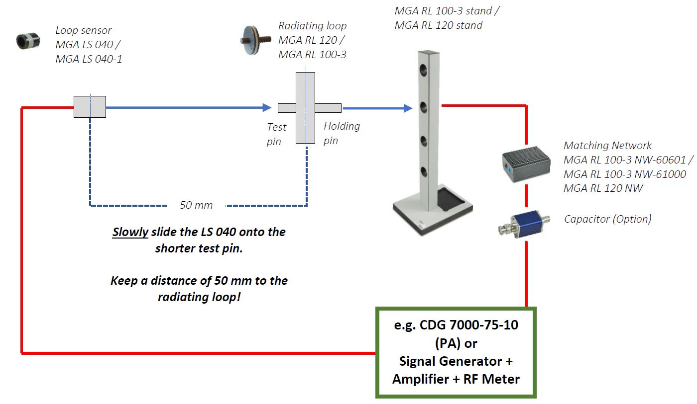
EN 61000-4-39 describes magnetic field tests in the near field in two frequency ranges from 9 kHz - 150 kHz and from 150 kHz - 26 MHz. For both ranges, complete sets are offered for operation on a typical RF broadband amplifier. (Take the required sets for your tests from the “Equipment or complete sets..” compilation).

Frequency range 9 kHz – 150 kHz Frequency range 150 kHz – 26 MHz 
IEC 61000-4-39 IEC 61000-4-39

RL 120 transmitting coil with LS 040 loop sensor (electrostatic shielded) from MIL-STD-461:

  • Field strengths 1 ... 30 A/m
  • Modulation AM 80% 1 kHz sine
  • Illumination area 100 x 100 mm
  • Distance 50 ±3 mm
  • Test frame with coil mounting holes on 150, 250, 350, 450 mm.
  • Matching network with 2x10 Ω series resistors for matching to RF amplifiers at low frequencies
  • Power consumption < 46 dBm (just under 40 W) at 150 kHz and 30 A/m incl. modulation

For the upper-frequency range, the 61000-4-39 defines a new 100 mm transmitting coil with 3 turns. The generated field is measured with a loop sensor, also newly defined, with a diameter of 40 mm and only 1 turn. In the standard, only the loop sensor is electrostatically shielded. To prevent the radiation of an electric field at higher frequencies, the RL 100-3 is also electrostatically shielded and symmetrically controlled via a balun:

  • Field strengths 0.1 ... 3 A/m: A preamplifier (PA) is required to measure this low field strength!
  • Pulse modulation with 50% duty cycle and 2 Hz or 1 kHz modulation frequency§ Illumination area 80 x 80 mm
  • Test frame with coil mounting holes on 120, 200, 280, 360, 440 mm
  • Matching network with balun for balanced drive and 2 x 10 Ω series resistors for matching to RF amplifiers at low frequencies
  • Power consumption < 44 dBm (appr. 25 W) at 26 MHz and 3 A/m
IEC 60601-1-2 IEC 60601-1-2

In 60601-1-2, magnetic field tests are required with RL 120, but only at two defined frequencies with modified levels and modula¬tions:

  • 30 kHz with 8 A/m continuous wave
  • 134.2 kHz with 65 A/m, 2.1 kHz pulse-modulated

The required power here is max. 46.3 dBm (approx. 43 W).

To reduce the power to approx. 43.1 dBm (approx. 20 W), an optional resonant capacitor can be connected in series.

In 60601-1-2, magnetic field tests are required with RL 100, but only at 13.56 MHz. Level and modulation have also been changed here.

  • 13.56 MHz with 7.5 A/m, 100 kHz pulse modulation

Without resonant network, more than 49.3 dBm (approx. 85 W) is required. With resonant network, the power requirement is reduced to about 35 dBm (approx. 3.2 W).

Thus, 30 A/m can be achieved for a short time with about 50 W amplifier power.

VSWR is < 1:2 in resonance.


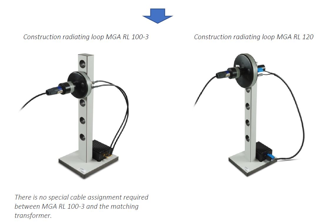
Construction coil set


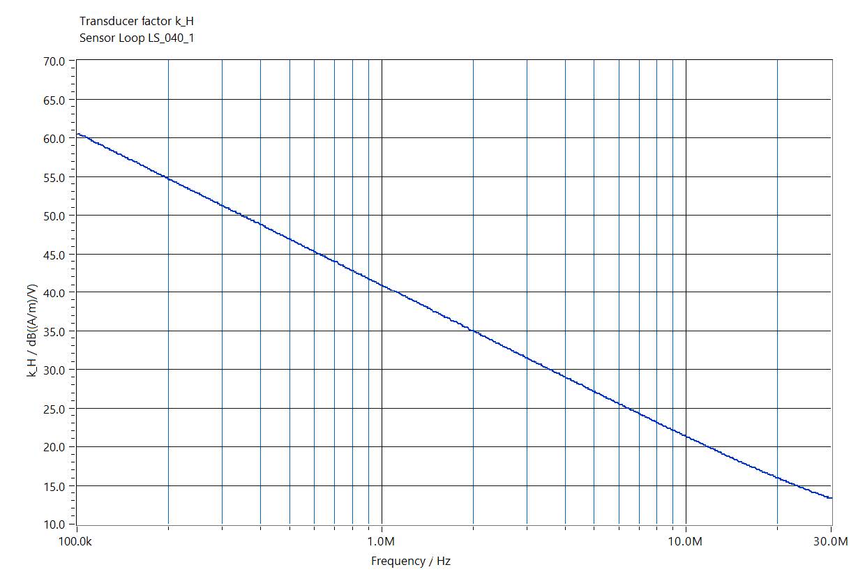
Sensor Loop LS 040-1, Transducer Factor


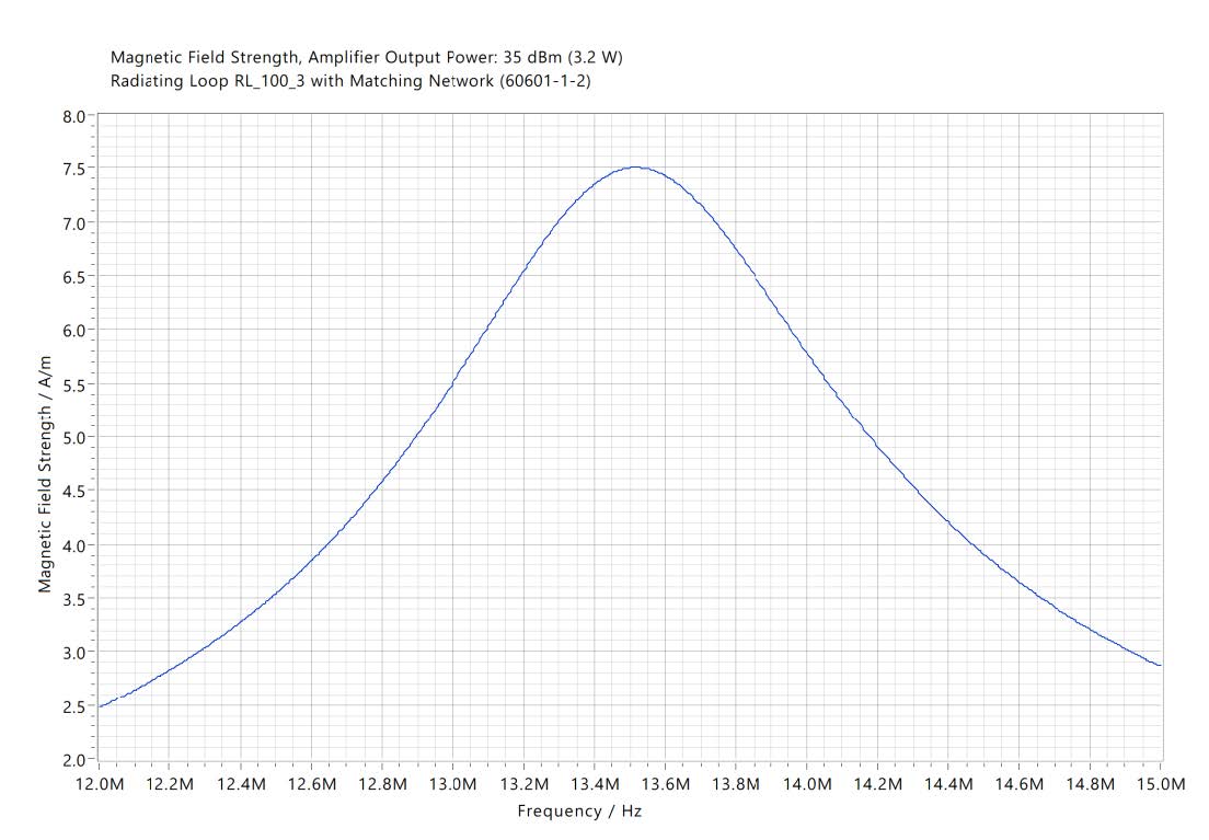
Radiating loop RL 100-3, Magnetic Field Strength
Magnetic field strength, amplifier output power: 35 dBm (3.2 W)
Radiating loop RL 100-3, with the matching network (60601-1-2)

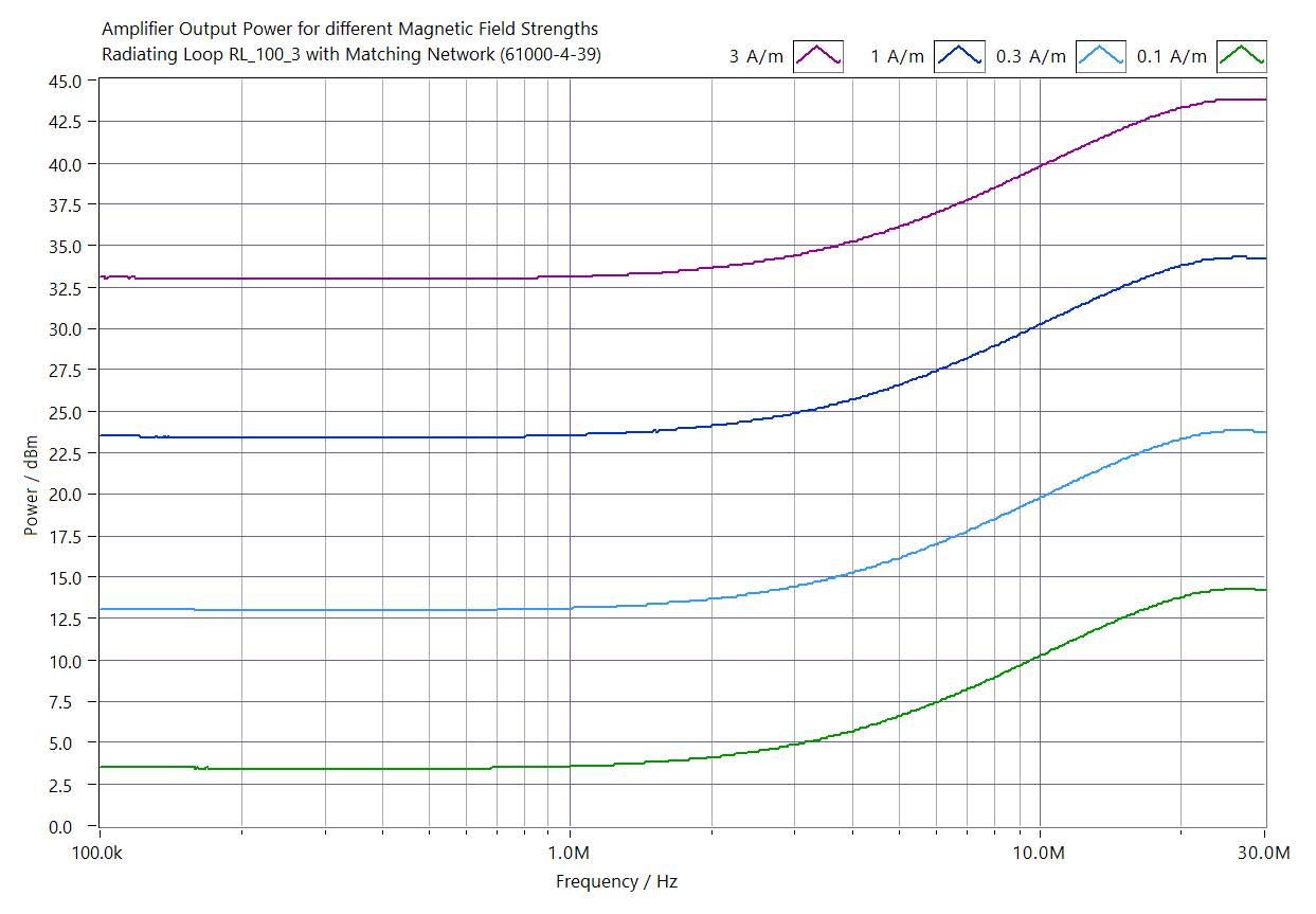
Radiating loop RL 100-3, Amplifier Output Power for different Magnetic Field Strengths
Amplifier output power for different magnetic field strengths
Radiating loop RL 100-3, with the matching network (61000-4-39)

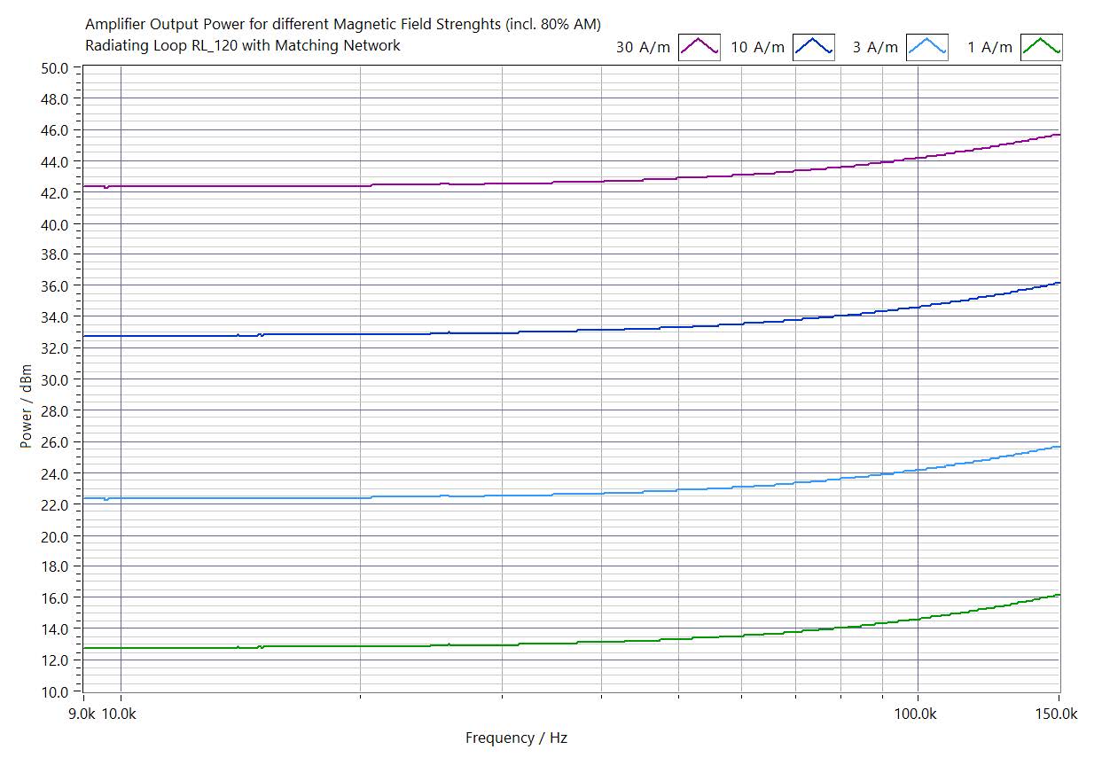
Radiating loop RL 120, Amplifier Output Power for different Magnetic Field Strengths
Amplifier output power for different magnetic field strengths (incl. 80% AM)
Radiating loop RL 120, with matching network

For IEC 60601-1-2, approxi-mately 46.3 dBm is required for 65 A/m at 134.2 kHz with the same setup. This can be realized with the 75W-10 kHz amplifier. With a resonance capacitor in series with the matching network, this required power can be halved to 43.1 dBm.


The following complete sets of equipment is required for the tests:
Generator, software, and measurement

  • CDG 7000-75-10 - 10 kHz - 250 MHz, 75 Watt, amplifier, RF Generator, RF Meter x3 (monitored level, forward & reverse power) only IEC 60601-1-2
  • Option: PreAmp 150kHz-26MHz -4-39
    Preamplifier for CDG 7000-75-10 for tests according to IEC 61000-4-39
    (sensor coil LS 040-1 provides too low an output level for the CDG 7000 for the lowest standard levels at low frequencies)
  • HELIA 7-MGA software: The system includes all cabling and HELIA 7 software required to meet the standard’s requirements.


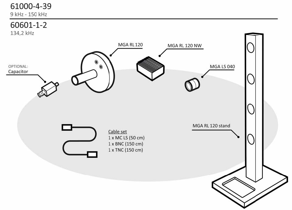
Complete set for frequency range: 9 kHz – 150 kHz
Article No.: Set 9kHz-150kHz -1-2/-4-39

Coil set RL-120 & LS-040 incl. stand and matching network for tests according to IEC 60601-1-2 Ed. 4.1 (30 kHz, 134.2 kHz) and IEC 61000-4-39 (9 kHz to 150 kHz)

  • MGA RL 120 – Radiating loop 120 mm as specified in IEC 61000-4-39 for 9 kHz – 150 kHz, IEC / EN 60601-1-2 and MIL-STD-461 / RS101, 3 m cable
  • MGA RL 120 NW – Matching Network for MGA RL 120, matches loop to 50 Ohms of the CDG 7000 amplifier acc. to IEC 61000-4-39 and IEC / EN 60601-1-2 for Immunity to magnetic fields 9 kHz - 150 kHz
  • MGA RL 120 Stand – Stand for MGA RL 120 for tests
  • MGA LS 040 – Loop sensor 40 mm
  • Cable set

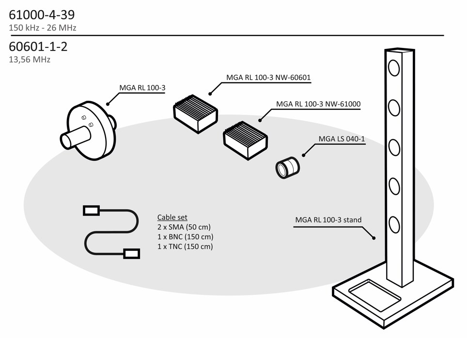
Complete set for frequency range: 150 kHz – 26 MHz
Article No.: Set 150kHz-26MHz -1-2/-4-39
Coil set RL-100-3 & LS-040-1 incl. stand and matching network for tests according to IEC 61000-4-39 (150 kHz to 26 MHz) and IEC 60601-1-2 (13.56 MHz)

  • MGA RL 100-3 – Radiating loop as specified in IEC 61000-4-39 and IEC / EN 60601-1-2 for 150 kHz – 26 MHz
  • MGA LS 040-1 – Loop sensor 40 mm that attaches to MGA RL 100-3 at the correct distance of 50 mm as specified in IEC 61000-4-39 and IEC / EN 60601-1-2
  • MGA RL 100-3 stand – for tests in stronger magnetic fields
  • MGA RL 100-3 NW-60601 – Matching Network 60601 for MGA RL 100-3, matches MGA RL 100-3 to the IEC 60601-1-2 requirements
  • MGA RL 100-3 NW-61000 – Matching Network 61000 for MGA RL 100-3, matches MGA RL 100-3 to the IEC 61000-4-39 requirements
  • Cable set

Set -4-39 for frequency range: 150 kHz – 26 MHz
Article No.: Set 150kHz-26MHz -4-39
Coil set RL-100-3 & LS-040-1 incl. stand and matching network for tests according to IEC 61000-4-39 (150 kHz to 26 MHz)

  • MGA RL 100-3 – Radiating loop as specified in IEC 61000-4-39 and IEC / EN 60601-1-2
  • MGA LS 040-1 – Loop sensor 40 mm that attaches to MGA RL 100-3 at the correct distance of 50 mm as specified in IEC 61000-4-39 and IEC / EN 60601-1-2
  • MGA RL 100-3 stand – for tests in stronger magnetic fields
  • MGA RL 100-3 NW-61000 – Matching Network 61000 for MGA RL 100-3, matches MGA RL 100-3 to the IEC 61000-4-39 requirements
  • Cable set


Set -1-2 for frequency range: 150 kHz –26 MHz
Article No.: Set 150kHz-26MHz -1-2
Coil set RL-100-3 & LS-040-1 (incl. stand and matching network) for tests according to IEC 60601-1-2 (13.56 MHz)

  • MGA RL 100-3 – Radiating loop as specified in IEC 61000-4-39 and IEC / EN 60601-1-2
  • MGA LS 040-1 – Loop sensor 40 mm that attaches to MGA RL 100-3 at the correct distance of 50 mm as specified in IEC 61000-4-39 and IEC / EN 60601-1-2
  • MGA RL 100-3 stand – for tests in stronger magnetic fields
  • MGA RL 100-3 NW-60601 – Matching Network 60601 for MGA RL 100-3, matches MGA RL 100-3 to the IEC 60601-1-2 requirements
  • Cable set


Upgrade for frequency range: 9 kHz – 150 kHz (with existing equipment RL 120 / LS 040)
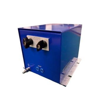
Article No.: Upgrade 9kHz-150kHz -4-39
Stand and matching network for coil set RL-120 & LS-040 for tests according to IEC 61000-4-39 (9 kHz to 150 kHz)

  • MGA RL 120 NW – Matching Network for MGA RL 120, matches loop to 50 Ohms of the CDG 7000 amplifier acc. to IEC 61000-4-39 and IEC / EN 60601-1-2 for Immunity to magnetic fields 9 kHz - 150 kHz
  • MGA RL 120 Stand – Stand for MGA RL 120 for tests
  • Cable set


Capacitor
Article No.: Capacitor 1/2W 134,2 kHz -1-2
The capacitor in housing (resonance matching) for RL-120 with matching network BNC male/ BNC female. When testing for IEC 60601-1-2: 134.2 kHz, 65 A/m, the required power can be halved from 46.3 dBm / 43 W to 43.1 dBm / 20 W with the optional resonance matching. The capacitor in the housing is plugged in front of the matching network.


Added system advantage
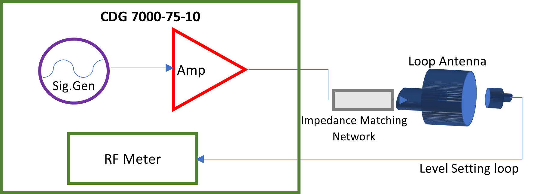
  • EUT monitoring: with Digital TTL signals & analog 0-10 VDC (automate threshold and report)
  • EUT Fail port: Stop test or mark report
  • SCPI interface control for universal support (11452-4)
  • Conducted immunity testing to IEC 61000-4-6, ISO, MIL, and other standards with the use of additional accessories CDNs, EMC clamps, BCI clamps


OTHER PRODUCTS IN THE SAME CATEGORY:
Loading...