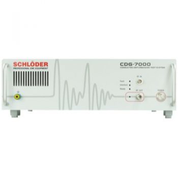

CDG 7000 Conducted Immunity, (4)10 kHz - 400MHz
- Integrated RF signal generator, RF power amplifier, 3-channel RF voltmeter, and directional coupler
- Generator frequency range from 9 kHz to 1.2 GHz, usable from 4 kHz
- RF amplifier configurations available from 25 W to 200 W
- Frequency coverage options from 10 kHz to 400 MHz, depending on model
- HELIA 7-Basic software included for test control, reporting, and EUT monitoring
- External amplifier expansion through the second generator output
- SCPI command set for integration into automated EMC software systems
PARTNER:
MARKETS:
CATEGORIES:
TEST STANDARDS:
Select Options/Sizes:

Software HELIA 7
Setup Diagrams
Data Sheet
SPECIFICATIONS
CDG 7000 Conducted Disturbances Test System
The Schlöder CDG 7000 is a compact conducted-disturbance test system for RF conducted immunity testing, magnetic-field-related immunity applications, and Bulk Current Injection testing. The system combines the primary instruments required for IEC / EN 61000-4-6 testing into a single integrated platform: RF signal generator, RF power amplifier, 3-channel RF voltmeter, and directional coupler.
The CDG 7000 is designed for direct disturbance injection onto power, signal, and control lines using coupling/decoupling networks, EM clamps, and BCI injection probes. This allows the equipment under test to remain in its normal operating configuration while RF disturbances are applied to connected cables and interfaces.
Standards and Applications
The CDG 7000 supports a wide range of conducted RF immunity and magnetic field-related test requirements, depending on the selected model and accessories.
| Standard / Application | Typical Use |
|---|---|
| IEC / EN 61000-4-6 | Conducted immunity to RF disturbances induced onto cables |
| IEC 60601-1-2 Ed. 4.1 | Medical electrical equipment EMC immunity testing |
| IEC 61000-4-39 | Close proximity radiated fields / magnetic field-related immunity test setups |
| MIL-STD-461 CS114 | Bulk cable injection susceptibility testing |
| ISO 11452-4 | Automotive Bulk Current Injection Testing |
| NAMUR | Industrial immunity applications |
| IEC 61326-3-2 | Functional safety-related immunity applications, depending on configuration |
Key Features
- Integrated RF signal generator, RF power amplifier, 3-channel RF voltmeter, and directional coupler
- Generator frequency range from 9 kHz to 1.2 GHz, usable from 4 kHz
- RF amplifier configurations available from 25 W to 200 W
- Frequency coverage options from 10 kHz to 400 MHz, depending on model
- CDG 7000-200 supports BCI testing up to 500 mA closed loop with the appropriate accessories
- Optional CDG 7000-200-4 amplifier extends the CDG 7000-200 system downward to 4 kHz – 1 MHz
- HELIA 7-Basic software included for test control, reporting, and EUT monitoring
- HELIA 7 BCI software available for BCI testing
- External amplifier expansion through the second generator output
- SCPI command set for integration into automated EMC software systems
- Interfaces include USB and LAN, with optional GPIB
- Temperature measurement input for monitoring the BCI clamp temperature
- Input for external pulse modulation
- Configurable digital 8-channel user port
- EUT monitor input and EUT failed input for automated test evaluation
System Overview
The CDG 7000 is well-suited for laboratories that need a compact, integrated conducted-immunity platform. By combining multiple instruments into one system, the CDG 7000 helps reduce rack space, setup complexity, cabling, and integration time.
The system can be configured for IEC 61000-4-6 testing using CDNs or EM clamps, for ISO 11452-4/MIL-STD-461 CS114 BCI testing using injection and monitoring probes, and for IEC 60601-1-2 Ed. 4.1 / IEC 61000-4-39 related test configurations with the proper accessories and software.
Available Versions
| Model | Frequency Range | RF Amplifier Power | Maximum Test Level | Included Software / Interfaces | Notes |
| CDG 7000-25 | 10 kHz – 250 MHz | 25 W | 10 V, 15 V without 6 dB, with 80% AM | HELIA 7-Basic, USB, LAN | Integrated directional coupler |
| CDG 7000-75 | 100 kHz – 400 MHz | 75 W | 30 V, 40 V without 6 dB, with 80% AM | HELIA 7-Basic, USB, LAN | Integrated directional coupler |
| CDG 7000-75-10 | 10 kHz – 400 MHz | 75 W | 30 V, 40 V without 6 dB, with 80% AM | HELIA 7-Basic, USB, LAN | Wider low-frequency coverage |
| CDG 7000-200 | 100 kHz – 400 MHz | 200 W | 30 V, 40 V without 6 dB, with 80% AM, up to 500mA | HELIA 7-Basic, USB, LAN | Supports BCI testing up to 500 mA closed loop with appropriate accessories |
| CDG 7000-200 with CDG 7000-200-4 | 4 kHz – 1 MHz extension plus 100 kHz – 400 MHz main amplifier range | 200 W main amplifier plus external low-frequency extension amplifier | Application dependent up to 500mA | HELIA 7-Basic, USB, LAN | Lower-frequency extension for CDG 7000-200 |
| CDG 7000-E | External amplifier version | No internal RF amplifier | Depends on the external amplifier | See the separate configuration | For users requiring flexible external RF amplifier selection |
 The models listed can be supplemented with additional accessories and combined with one another.
RF Power Amplifier Specifications
| Parameter | 25 W Version | 75 W Version | 75 W / 10 k Version | 200 W Version | No Amp |
| Model | CDG 7000-25 | CDG 7000-75 | CDG 7000-75-10 | CDG 7000-200 | CDG 7000-E |
| Frequency Range | 10 kHz – 250 MHz | 100 kHz – 400 MHz | 10 kHz – 400 MHz | 100 kHz – 400 MHz | Depended on amplifier |
| Low Frequency Extension | — | — | — | CDG 7000-200-4: 4 kHz – 1 MHz |
|
| Nominal Output Power | 25 W | 75 W | 75 W | 200 W | |
| Linear Power at 1 dB Compression | 20 W | 50 W | 50 W | 100 W | |
| Gain | 46 dB nominal | 51 dB nominal | 51 dB nominal | 56 dB nominal | |
| Flatness | ±1.5 dB max. | ±1.5 dB max. | ±1.5 dB max. | ±1.5 dB max. | |
| Input Power for Rated Output | 1 mW / 0 dBm | 1 mW / 0 dBm | 1 mW / 0 dBm | 1 mW / 0 dBm | |
| Input / Impedance | SMA / 50 Ω | SMA / 50 Ω | SMA / 50 Ω | SMA / 50 Ω | |
| Output / Impedance | N / 50 Ω | N / 50 Ω | N / 50 Ω | N / 50 Ω | |
| Input VSWR | 1.5:1 max. | 1.5:1 max. | 1.5:1 max. | 1.5:1 max. | |
| Harmonic Distortion | < -20 dBc @ 20 W | < -20 dBc @ 50 W | < -20 dBc @ 50 W | < 20 dBc @ 100 W | |
| Spurious | < -75 dBc to 10 W | < -75 dBc to 10 W | < -75 dBc to 10 W | < -75 dBc to 10 W | |
| Directional Coupler | |||||
| Power Rating | 100 W | 100 W | 100 W | 500 W | 200W (Optional 500W) |
| Frequency Range | 10 kHz – 500 MHz | 100 kHz – 500 MHz | 10 kHz – 500 MHz | 10 kHz – 400 MHz | 10 kHz – 1 GHz |
| Coupling | 40 dB | 40 dB | 40 dB | 50 dB | 40 dB (50dB) |
RF Generator Specifications
| Parameter | Specification |
| RF Outputs | Two switchable SMA outputs; one output used at a time |
| Frequency Range | 9 kHz – 1.2 GHz, usable from 4 kHz |
| Frequency Resolution | 1 Hz |
| Output Level Range | 0 to -63 dBm |
| Output Level Resolution | 0.1 dB |
| Harmonics | < 30 dBc |
| Spurious | < 45 dBc |
| Internal AM | 0 – 100%, 1% resolution |
| External AM | 0 – 100%, 1 V = 100%, BNC input |
| Internal Pulse Modulation | 5 – 95%, 1% resolution |
| External Pulse Modulation | DC – 1 MHz, 3.3 / 5 V CMOS / TTL, BNC input |
LF Generator Specifications
| Parameter | Specification |
| Connector | BNC jack |
| Frequency Range | 1 Hz – 100 kHz |
| Frequency Resolution | 0.1 Hz |
| Signal Types | Sine, square, triangular |
| Amplitude | 0 – 1 V |
RF Voltmeter Specifications
| Function | Connector | Frequency Range | Measuring Range |
| RF Voltmeter, Test Level | BNC jack | 9 kHz – 1.2 GHz, usable from 4 kHz | -40 to +30 dBm |
| RF Voltmeter 2 + 3, Forward / Reverse Power | 2 x SMA | 9 kHz – 1.2 GHz, usable from 4 kHz | -40 to +33 dBm plus directional coupler, typically 40 dB |
Monitoring, Control, and Interfaces
| Module / Function | Specification |
| EUT Monitor Input Voltage | 0 to 10 V DC |
| EUT Monitor Resolution | 2.5 mV |
| EUT Monitor Input Impedance | 100 kΩ |
| EUT Failed Input Signal | 3.3 / 5 V CMOS / TTL |
| EUT Failed Detection Mode | Status or edge controlled |
| Temperature Measurement | 10 – 100 °C, PT1000, resolution < 1 °C |
| USB Interface | USB 2.0, USB-B |
| LAN Interface | 100 Mbit, RJ45 |
| GPIB Interface | Optional, Centronics |
| Digital Outputs | 4-bit digital output, 5 V CMOS / TTL |
| Digital Inputs | 4-bit digital input, 5 V CMOS / TTL |
| Interlock | Closes at R < 1 kΩ |
General Specifications
| Parameter | Specification |
| Operating Temperature Range | 0 – 40 °C |
| Housing | 19-inch desktop case, 84 TE, 3 HE |
| Weight | Approx. 11 kg |
| Dimensions | Approx. 450 x 135 x 504 mm |
| AC Input | 100 – 240 VAC, 50 / 60 Hz |
Included Scope of Delivery
| Included Item | Description |
| Power Cable | V-Lock power cable |
| Ground Terminal | Included |
| USB Cable | Included |
| BNC Connector / 50 Ω Resistor | Included |
| Socket Strips and SMA Fixed Cables | 2 x socket strips and 3 x SMA fixed cables, already connected |
| HELIA Software Dongle | USB dongle for HELIA software |
| User Manual | Included |
| USB Stick | Includes calibration certificate, user manual, and HELIA software |
| RF Cable L0023 | BNC male to N male, 1.5 m |
| RF Cable L0068 | N connector to N connector, 1.5 m |
| RF Cable L0024 | BNC male to TNC male, 1.5 m |
| RF Cable L0069 | N connector to angled BNC connector, 30 cm, for 75 W version only |
Typical Test Configurations
IEC / EN 61000-4-6 Conducted Immunity
For IEC 61000-4-6 testing, the CDG 7000 is used with coupling/decoupling networks, EM clamps, or other suitable coupling devices. The generator produces the RF disturbance signal while the integrated amplifier, RF metering, and directional coupler support level setting, monitoring, and test execution.
MIL-STD-461 CS114 and ISO 11452-4 BCI
For BCI testing, the CDG 7000 can be configured with a BCI injection probe and a current monitoring probe. The CDG 7000-200 configuration supports BCI testing up to 500 mA closed loop when used with the correct accessories.
IEC 60601-1-2 Ed. 4.1 / IEC 61000-4-39
The CDG 7000-75-10 is well-suited for medical EMC immunity test configurations requiring low-frequency RF conducted immunity and magnetic field-related test setups. Additional accessories and test fixtures may be required depending on the final test standard and level.

Accessories
Coupling Networks and CDN Accessories (See separate Page)
| Accessory | Description / Use | Picture |
| CDG CDN-M1 | Coupling/decoupling network | |
| CDG CDN-M2 | Coupling/decoupling network | |
| CDG CDN-M3 | Coupling/decoupling network | |
| CDG CDN-M4 | Coupling/decoupling network | |
| CDG CDN-M5 | Coupling/decoupling network | |
| CDG CDN-M2+3 | Coupling/decoupling network | |
| CDG CDN-M1/-M2/-M3-10k | 10 kHz coupling/decoupling network version | |
| CDG CDN-M4/-M5-10k | 10 kHz coupling/decoupling network version | |
| CDG CDN-M2/-M3-125A | High-current coupling/decoupling network | |
| CDG CDN-M4/-M5-125A | High-current coupling/decoupling network | |
| CDG CDN-L1 | Coupling/decoupling network | |
| CDG CDN-L1-32A | 32 A coupling/decoupling network | |
| CDG CDN-AF2 | Coupling/decoupling network | |
| CDG CDN-AF3 | Coupling/decoupling network | |
| CDG CDN-AF4 | Coupling/decoupling network | |
| CDG CDN-AF5 | Coupling/decoupling network | |
| CDG CDN-AF6 | Coupling/decoupling network | |
| CDG CDN-AF8 | Coupling/decoupling network | |
| CDG CDN-AF2/-AF3-10k | 10 kHz coupling/decoupling network version | |
| CDG CDN-AF4/-AF5-10k | 10 kHz coupling/decoupling network version | |
| CDG CDN-RJ45 | RJ45 coupling/decoupling network | |
| CDG CDN-RJ45-10k | 10 kHz RJ45 coupling/decoupling network | |
| CDG CDN D 100 | Coupling/decoupling network accessory | |
| CDG CDN-T2 | Coupling/decoupling network | |
| CDG CDN-T4 | Coupling/decoupling network | |
| CDG CDN-T8 | Coupling/decoupling network | |
| CDG CDN-T2/-T4/-T8-10k | 10 kHz T-series coupling/decoupling network versions | |
| CDG CDN-S1 | Coupling/decoupling network | |
| CDG CDN-S1-75 Ohm | 75 Ω S1 coupling/decoupling network | |
| CDG CDN-S2 | Coupling/decoupling network | |
| CDG CDN-S3 | Coupling/decoupling network | |
| CDG CDN-S4 | Coupling/decoupling network | |
| CDG CDN-S9 | Coupling/decoupling network | |
| CDG CDN-S15 | Coupling/decoupling network | |
| CDG CDN-S25 | Coupling/decoupling network | |
| CDG CDN-CAN-L4 | CAN coupling/decoupling network | |
| CDG CDN-CAN-L5 | CAN coupling/decoupling network | |
| CDG CDN-RJ45-S | RJ45 coupling/decoupling network | |
| CDG CDN-HDMI | HDMI coupling/decoupling network | |
| CDG CDN-FireWire | FireWire coupling/decoupling network | |
| CDG CDN-USB-3.0-Z | USB 3.0 coupling/decoupling network | |
| CDG CDN-USB-3.0-P | USB 3.0 coupling/decoupling network | |
| CDG CDN-USB Typ-C | USB Type-C coupling/decoupling network | |
*Other CDNs available on request
Calibration Accessories for CDNs
To calibrate a coupling/decoupling network, the following accessories are used on the AE and EUT side.
| Calibration Accessory | Description | Picture |
| CDG A 41xx | Connection adaptor with laboratory plug for the corresponding CDN | |
| CDG A 4100 | Mounting plate with 50 / 150 Ω transition and 50 Ω termination for AE side | |
| CDG 4110 | 50 / 150 Ω adaptor | |
| First CDN Calibration Setup | 2 x CDG A 41xx plus 2 x CDG A 4100 | |
| Additional CDN Calibration Setup | 2 x CDG A 41xx for each additional coupling network | |
| Note | Depending on the signal, termination can sometimes be omitted on the AE side. Contact Absolute EMC for configuration support. |
Clamps, BCI Probes, Current Monitoring Probes, Attenuators, and Terminations
| Accessory | Description / Use | Picture |
| CDG CDN EMCL-20 | EM coupling clamp for cables up to 20 mm diameter; includes calibration set and factory calibration | 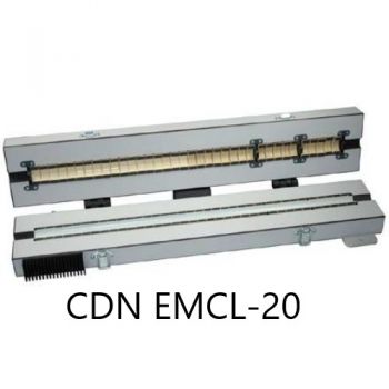 |
| CDG CDN EMCL-35 | EM coupling clamp for cables up to 35 mm diameter; includes calibration set and factory calibration | 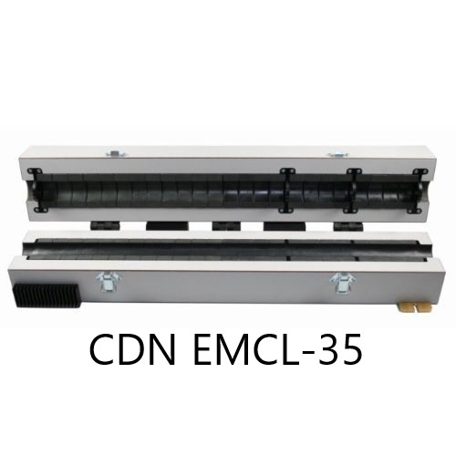 |
| CDG CDN-EMCL-NW_10 | Matching network for CDN EMCL-20, extending operation down to 10 kHz | 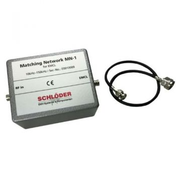 |
| CDG CDN ABCL-20 | Decoupling clamp for cables up to 20 mm diameter; used for additional decoupling in IEC / EN 61000-4-6 immunity testing | 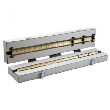 |
| CDG CDN ABCL-35 | Decoupling clamp for cables up to 35 mm diameter; used for additional decoupling in IEC / EN 61000-4-6 immunity testing | 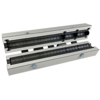 |
| CDG CDN BCI-P1 | Bulk Current Injection probe; 1 – 400 MHz; for cables up to 40 mm diameter; includes calibration set | 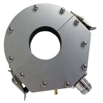 |
| CDG CDN BCI-P1_MT-1 | Additional transformer for CDN BCI-P1; 1 – 400 MHz; for cables up to 40 mm diameter; includes calibration set | 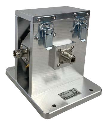 |
| CDG CMP-45 | Foldable current monitoring probe, 10 kHz – 400 MHz, for cables up to 45 mm diameter | 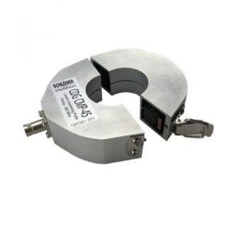 |
| CDG A CMP-45 | Calibration set for CDG CMP-45 | 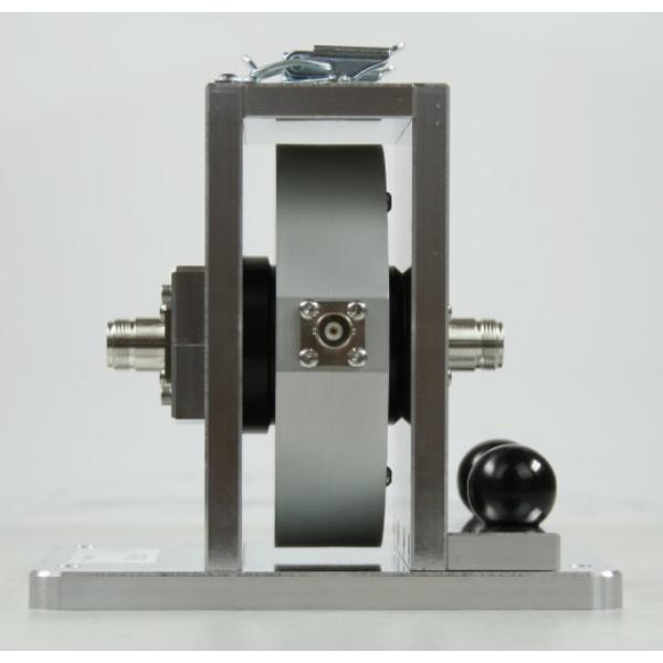 |
| CDG CMP-46 | Non-foldable current monitoring probe, 10 kHz – 400 MHz, for cables up to 46 mm diameter | 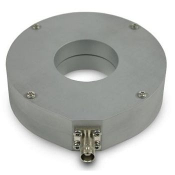 |
| CDG A CMP-46 | Calibration set for CDG CMP-46 | |
| CDG 7006-20W | 6 dB attenuator, 20 W | |
| CDG 7006-100W | 6 dB attenuator, 100 W |  |
| CDG 7020-20W | 20 dB attenuator, 20 W | |
| CDG A 50 | BNC termination, 50 Ω, 1 W | |
| CDG A 50-10W | BNC termination, 50 Ω, 10 W | |
| Pre-Amp for CS 114 | Preamplifier for low-level testing to expand the range of the internal Voltmeter/powermeter | |
| CDG 7000-200-4 | Low-frequency extension amplifier for CDG 7000-200, 4 kHz – 1 MHz | |
| Helia 7 - BCI | Software extension for BCI, ISO/MIL tests. |
MIL-STD-461: CDG 7000-75-10 or [CDG 7000-200 + CDG 7000-200-4] Accessories: CDG CDN BCI-P1_MT1, CDG 7020-20W, CDG CMP 45 +CDG CMP A 45, 2x CDG A 50-100W, Pre-Amp for CS 114, Helia-BCI
DO-160: CDG 7000-75-10 (limited for CAT Y) or [CDG 7000-200 + CDG 7000-200-4] Accessories: CDG CDN BCI-P1_MT1, CDG 7020-20W, CDG CMP 45, CDG A 50-100W, Pre-Amp for CS 114, Helia-BCI
ISO 11452-4: CDG 7000-75 or CDG 7000-75-10 or CDG 7000-200 Accessories: CDG CDN BCI-P1, CDG 7020-20W, CDG CMP 45, CDG A 50-100W, Helia-BCI
Why Buy from Absolute EMC?
Absolute EMC supports EMC laboratories with equipment selection, system configuration, installation, training, and application support. The CDG 7000 can be configured for a broad range of conducted RF immunity applications, including commercial, medical, automotive, military, aerospace, and industrial EMC test requirements.
Contact Absolute EMC to review your required standards, test levels, cable types, EUT power requirements, and coupling method so we can recommend the correct CDG 7000 model and accessory configuration.
Request a Quote
To configure a CDG 7000 system, please provide the applicable standards, frequency range, required test level, EUT power configuration, cable types, and whether CDN, EM clamp, or BCI injection testing is required. Absolute EMC can help define the correct generator, amplifier power level, software, coupling networks, clamps, probes, calibration accessories, and RF cabling for your application.
OTHER PRODUCTS IN THE SAME CATEGORY:


400 - 6112, 2-Ch, 250kS/s, AnyWave Control Unit
400 - 6361, 2-Ch, 2.8MS/s, AnyWave Control Unit
CDG 7000-75-10 Magnetic Immunity, 10 kHz - 400MHz, IEC 61000-4-39
CDG 7000-E Conducted Immunity Generator, (4)9 kHz - 1 GHz , No internal Amplifier

AN-ABCD-300, 300 Amp Artificial Network, EV HV Testing
CABAI20050, 200W, 50 A, 2:1, Audio Isolation Transformer
CDG 7000 Conducted Immunity, (4)10 kHz - 400MHz
CDG 7000-200 Conducted Immunity, 4 kHz - 400MHz, 200Watts
MAG 1000, 120A/m CW, 1100Am Short Duration, Power Frequency Magnetic Field
240-1C, 0-240V, 27-2000+kW, DC Power Supply, Sink/Source
320-1C, 0-320V, 36-2000+kW, DC Power Supply, Sink/Source
1500-1C, 0-1500V, 27-2000+kW, DC Power Supply, Sink/Source
60-1C, 0-60V, 9-2000+kW, DC Power Supply, Sink/Source
500-1C, 0-500V, 9-2000+kW, DC Power Supply, Sink/Source
1000-1C, 0-1000V, 18-2000+kW, DC Power Supply, Sink/Source
80-1C, 0-80V, 9-2000+kW, DC Power Supply, Sink/Source
160-1C, 0-160V, 18-2000+kW, DC Power Supply, Sink/Source
2000-1C, 0-2000V, 36-2000+kW, DC Power Supply, Sink/Source
3000-1C, 0-3000V, 54-2000+kW, DC Power Supply, Sink/Source

