Proper Field Probe Positioning and Coverage Techniques for MIL-STD-461H RS103 Testing
Proper Field Probe Positioning and Coverage Techniques for MIL-STD-461H RS103 Testing
MIL-STD-461H continues to improve the technical guidance surrounding RS103 radiated susceptibility testing, particularly regarding electric field probe positioning, field monitoring, illuminated volume coverage, and antenna beamwidth considerations. While RS103 has traditionally focused on generating a required electric field level at a single probe location, the updated guidance in Appendix A recognizes the practical challenges of accurately illuminating modern Equipment Under Test (EUT) configurations across extremely wide frequency ranges.

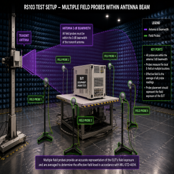
The standard now explicitly allows the use of multiple field probes and defines averaging techniques for determining the effective field level. This is an important step forward because successful RS103 testing is not simply about producing field strength. Proper RS103 testing requires ensuring the EUT is actually being illuminated correctly throughout the required frequency range without localized under-testing or unnecessary over-testing caused by antenna behavior, chamber reflections, beamwidth limitations, or field distortion.
The field surrounding an EUT is rarely uniform. The EUT itself affects the field. The chamber affects the field. The ground plane affects the field. The antenna beam changes shape continuously with frequency. Cable routing, rack geometry, absorbers, test tables, and nearby metallic surfaces all influence field distribution. Proper field probe placement is therefore one of the most important aspects of accurate RS103 testing.
MIL-STD-461H Appendix A states:
“The use of more than one sensor is acceptable provided all sensors are within the beamwidth of the transmit antenna. The effective field is determined by taking the average of the readings.”
This statement significantly changes how many engineers approach field monitoring.
Traditionally, many RS103 setups relied on a single field probe placed near the center of the test volume. While functional, this approach does not always represent the actual field exposure seen across the EUT. Single-probe testing can easily produce misleading results if the probe happens to sit inside a localized hot spot or null created by chamber reflections, antenna interaction, or EUT loading.
The standard further explains that field probes must remain within the antenna beam and inside the illuminated test volume. Probe placement must therefore be selected based on the antenna’s beamwidth at the frequency being tested.
This becomes critically important at higher frequencies.
As frequency increases, antenna beamwidth becomes narrower. Horn antennas especially become increasingly directional at high frequencies. The illuminated region may shrink significantly as frequency rises, even while the EUT size remains constant. Engineers must therefore continuously consider how much of the EUT is actually inside the antenna’s 3 dB beamwidth throughout the sweep.
Equation for window size from 3dB Beamwidth & Test Distance:

angle3dB = 3dB beamwidth
MIL-STD-461H discusses this directly:
“When testing large equipment, there may be a need to use antennas with wider beamwidths so that the EUT and sensor are within the 3 dB beamwidth. It may also be achieved by moving the antenna farther away to satisfy the requirement.”
This is one of the most important practical statements in the standard.
Equation for Distance from 3dB Beamwidth & Window size you want

At lower frequencies, beamwidth is generally wide enough that a single antenna position may illuminate the entire EUT. However, at higher frequencies, especially above 1 GHz, the beam may only illuminate a portion of the EUT. In these situations, the EUT must often be “windowed.” The standard states that above 200MHz, multiple antenna positions are allowed.
Windowing refers to dividing the EUT into multiple illuminated sections or “windows” so that the entire EUT is eventually exposed to the required field level. This process is extremely important for large racks, tall cabinets, long cable assemblies, or wide systems where the antenna beam can no longer cover the full EUT volume at the highest frequencies.
The most critical mistake engineers make during windowing is determining the window size using lower frequency beamwidths. The proper approach is to determine the window size using the narrowest beamwidth, which occurs at the highest frequency for that antenna and antenna distance combination.
If a horn antenna only covers a 40 cm wide area at the top frequency, then the EUT must be divided into windows no larger than that illuminated region. The antenna or EUT must then be repositioned to fully cover the entire product.
In some cases, using a wider beamwidth antenna may be beneficial. A wider beam can significantly reduce the number of windows required, which can greatly reduce total test time. However, larger beamwidth antennas usually require more amplifier power to achieve the same field level because the energy is distributed across a larger illuminated area.
Another option is to move the antenna farther away from the EUT.
Increasing distance generally increases illuminated coverage because the beam expands over distance. This often improves field uniformity and allows larger portions of the EUT to remain inside the 3 dB beamwidth. The tradeoff is that significantly more amplifier power may be required to maintain the required field strength at the greater distance.
When sufficient amplifier power is available, moving the antenna farther away is often one of the best methods for improving overall illumination quality and reducing the total number of required windows.
Proper field probe placement must always account for these beamwidth effects.
The probe should never simply be placed wherever it is easiest mechanically. The probe location should represent the actual illuminated field region seen by the EUT. Placing the probe directly in front of the antenna or directly in front of the center of the EUT is not always ideal, although in some setups it may be unavoidable.
For larger EUTs, probes should typically be positioned:
- near the outside edges of the EUT,
- across the illuminated width,
- and in some cases above the EUT,
provided the probes remain within the antenna’s 3 dB beamwidth.
This becomes especially important for tall rack systems where vertical field variation can become significant.
A common and highly effective method for rack testing is placing probes:
- upper left,
- upper right,
- lower left,
- lower right,
- and optionally center.

Large EUT with 3 Window positions and 5 probes used for each position.
This arrangement gives a much better understanding of how the field is distributed across the full rack height and width.
For tabletop equipment, three probes are often ideal:
- left side,
- center,
- right side.

Below 1 GHz

Above 1 GHz
MIL-STD-461H explicitly allows this averaging methodology.
For example:

If the probes measure:
30 V/m,
22 V/m,
35 V/m,
then:

This averaging method greatly improves the representativeness of the field measurement compared to a single probe location.
Multiple probe monitoring also dramatically improves visibility into chamber behavior. It allows engineers to identify:
- standing waves,
- chamber nulls,
- reflections,
- antenna asymmetry,
- field collapse near edges,
- and localized overdrive conditions.
This significantly improves testing repeatability and reduces unnecessary over-testing.
The standard also emphasizes that probes must measure true electric field. Appendix A states:
“Sensors that detect magnetic field or power density and convert to electric field are not acceptable” under non-far-field conditions.
This is especially important below 1 GHz where near-field behavior and chamber interactions become more dominant.
Probe height is also discussed by the standard. For frequencies below 1 GHz, the probes should generally remain at least 30 cm above the ground plane to reduce boundary condition effects. At frequencies above 1 GHz, the probes should remain inside the antenna beam at heights representative of the EUT being illuminated.
Another critical factor often overlooked is probe response speed.
RS103 commonly uses 1 kHz square-wave modulation with 50 percent duty cycle modulation. Slow-response probes can distort modulation tracking and create unstable closed-loop field regulation. Fast-response probes capable of accurately tracking pulsed and square-wave modulation in real time provide significantly better field regulation and faster sweep stability.
Likewise, fast-response broadband power monitoring is equally important. Slow power meters may fail to properly capture amplifier behavior during modulation peaks, leading to field overshoot or inconsistent regulation.
Combining:
- proper beamwidth analysis,
- intelligent probe placement,
- multiple probe averaging,
- fast-response field sensing,
- and high-speed forward power monitoring,
creates a far more accurate and technically defensible RS103 test environment.
Ultimately, proper field probe positioning is not simply about satisfying a field reading. It is about ensuring the EUT is truly exposed to the intended electromagnetic environment throughout the entire illuminated test volume and across the entire frequency range.
As MIL-STD-461H continues evolving toward more realistic and repeatable immunity testing methodologies, intelligent field probe positioning and multi-probe monitoring represent some of the most important improvements EMC laboratories can implement to improve test quality, repeatability, and confidence in radiated immunity results.
Reference:
MIL-STD-461H 17 APRIL 2026 DEPARTMENT OF DEFENSE INTERFACE STANDARD REQUIREMENTS FOR THE CONTROL OF ELECTROMAGNETIC INTERFERENCE CHARACTERISTICS OF SUBSYSTEMS AND EQUIPMENT