Haefely ONYX VISION: A Game Changer for ESD Testing
ESD TESTING | ENGINEERING & APPLICATIONS
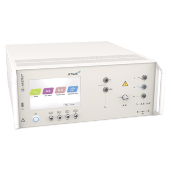
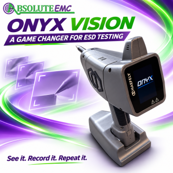
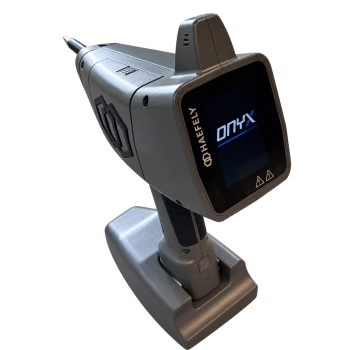
See the test point. Capture the settings. Return with confidence. Haefely ONYX VISION changes what an ESD test record can be. Its integrated camera puts visual evidence into the operator’s hand at the moment it matters, connecting the discharge location with the settings used there. For laboratories ready to spend less time reconstructing tests and more time engineering better products, this is a game changer.
Every ESD engineer knows the frustration: a test needs to be repeated, but a note leaves room for interpretation. Which edge of the connector? Which point on the enclosure? Which voltage level belonged to that photograph? ONYX VISION gives the laboratory a powerful answer: show the location and retain the settings with the image. That is a compelling reason for every lab running repeated ESD campaigns to put VISION on its equipment shortlist.
The original ONYX established the platform with a self-contained handheld design, interchangeable R/C networks and touch control. VISION builds on that foundation. Feedback from test engineers has helped shape changes that address everyday laboratory work, while evolving standards reinforce the value of clearly documented test conditions and repeatable test locations.
A picture is worth 1,000 words. A documented test point is worth even more.
The integrated camera makes the discharge location part of the test record. An operator can photograph each test point and retain the associated ESD settings with the image, making it easier to identify the conditions used at that location. Instead of relying on handwritten descriptions such as “left connector, upper corner,” the laboratory can keep a visual record of exactly where the simulator was applied.
Images can be saved and reviewed on a PC or through the iOS or Android app. The camera workflow can capture views before and after an impulse. This helps engineers document the test location, organize evidence for a report and return to the same point during troubleshooting or a later test campaign.
Pictures of every different test point and level can be priceless when it is time to reproduce a test.
Build a visual record that the next engineer can use, instead of leaving the location and settings open to interpretation.
Build a visual record that the next engineer can use, instead of leaving the location and settings open to interpretation.
The opportunity goes well beyond a better-looking report. Capture each distinct test point and level as part of the procedure, and the record becomes a practical guide for the next session. A colleague can see where the tip was placed. A development team can understand the location associated with a failure. A future retest can begin with a clearer reference. That is a meaningful improvement in the quality and usefulness of the evidence. Photographs strengthen reproducibility alongside controlled setup, calibration, environmental conditions and recorded equipment behavior.
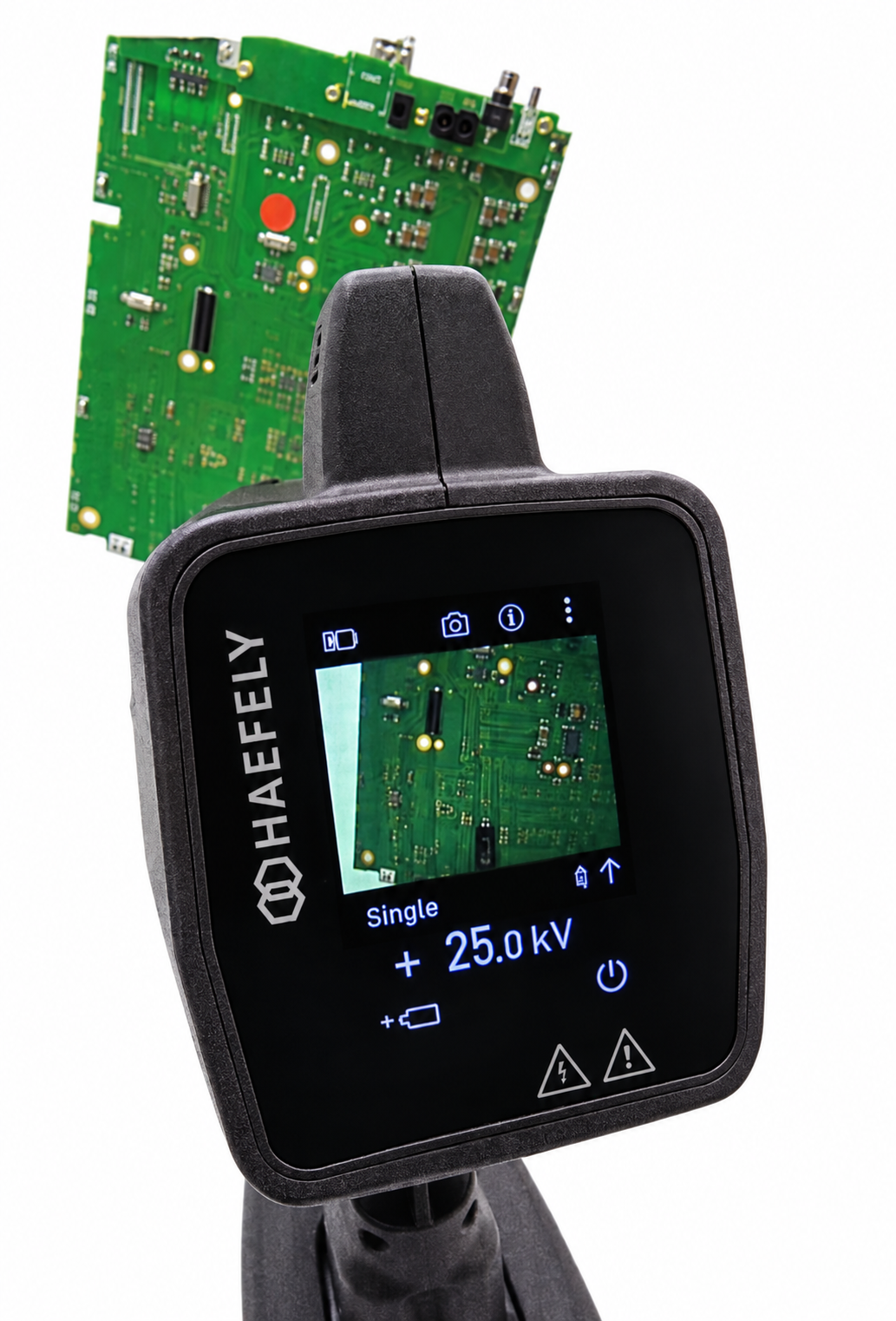
Imagine finishing a test session with the locations already photographed and their settings already associated, instead of facing a folder of disconnected images and a stack of notes. A single operator can capture photographs using the simulator, reducing reliance on a second person with a separate camera. Fewer photography interruptions, less manual matching and less uncertainty at reporting time create a real opportunity to shorten the overall test-and-documentation cycle. The required discharge count and standard test procedure still apply; the efficiency gain comes from removing avoidable work around them.
Less reconstruction. Faster reporting. Evidence worth keeping.
Free software and app control provides access from a PC, iOS device or Android device. The optional PRO version adds more advanced control, test-plan and reporting functions. For laboratories managing many points, polarities and voltage levels, this creates a more organized route from test execution to a documented result.
A useful record connects the product under test, the location, the ESD settings and the observed response. VISION’s photographs strengthen the location and settings portions of that record; the engineer still records the equipment’s behavior and applies the acceptance criteria required by the test plan.
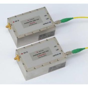
Bluetooth and Wi-Fi support wireless operation. An optical-fiber interface provides a connection route when wireless communication is restricted or unsuitable, including some secure test sites. Specify the required software version and interface hardware when configuring the system.
Built for the engineer who has hundreds of test points ahead
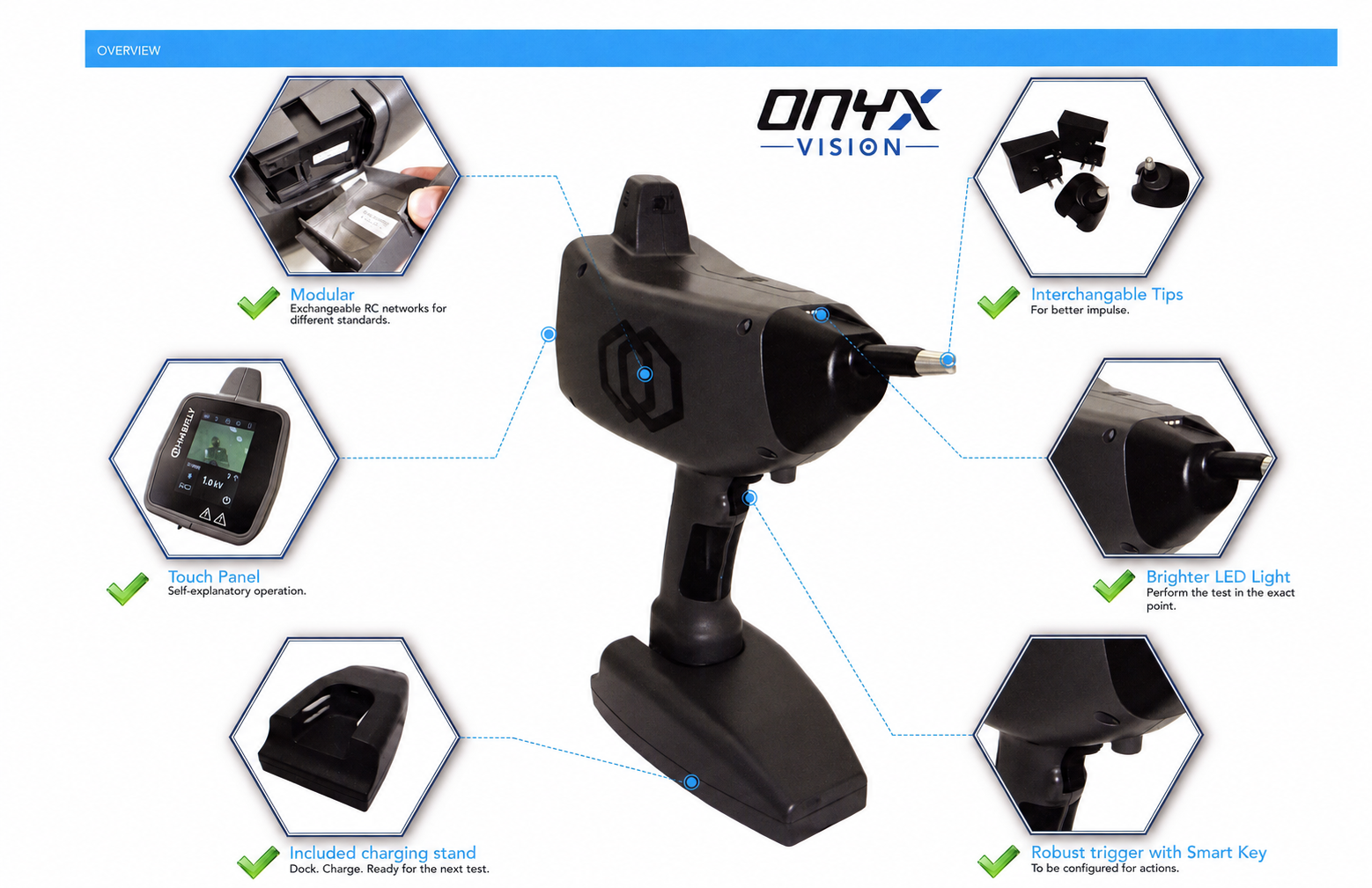
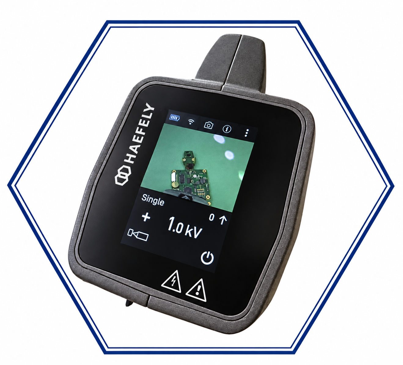
The new color touchscreen provides a clearer interface for setup and camera viewing. Its more responsive operation and navigation are intended to make repeated adjustments easier during a test session. The change is an improvement to the existing touch-control concept, rather than the first touchscreen in the ONYX family.
The redesigned multifunction trigger includes an upward toggle for configurable quick access. An operator can assign a frequently used action to reduce trips back to the screen. The original ONYX already offered a configurable smart-key concept; VISION refines the physical controls and their integration into the testing workflow.
More comfortable testing, from the first point to the last
Rubberized handle grips provide a more comfortable hold. Raised rubberized Haefely symbols on the housing also help resist sliding when the simulator is set down on a ground plane. These are practical changes for an instrument that is repeatedly lifted, aimed, repositioned and put down.
Despite adding the camera and new display, VISION remains in the same approximately 1.7 kg weight class as the original ONYX; the listed VISION weight is 1.69 kg. Its balanced handheld design keeps the load centered around the hand. The optional Absolute EMC Balancer has been redesigned for the new simulator so the support arrangement does not obstruct the camera.
The tip connections have been redesigned for more secure attachment through repeated use. The bright LED has moved to the top of the simulator to illuminate the test point for the camera and reduce shadows. Together, these changes help the operator position, see and document the discharge location.
An upright charging stand and USB-C charging
The included stand gives ONYX VISION an upright resting and charging position between tests. This is a charging stand, rather than a separate generator control base: the instrument remains an all-in-one handheld ESD simulator.
USB-C charging removes reliance on a dedicated proprietary charging connector. Use a compatible power supply and cable that meet Haefely’s charging requirements. A convenient charging connection and a defined resting place help keep the simulator ready for the next test sequence.
A voltage upgrade path that grows with the laboratory
ONYX VISION is offered in 8 kV, 16 kV and 30 kV configurations. Lower-voltage units can be upgraded in the field with a purchased unlock code: an 8 kV unit can move to 16 kV or 30 kV capability, and a 16 kV unit can move to 30 kV. Output remains limited to the enabled voltage range until an upgrade is applied.
This allows a laboratory to select the voltage range it needs today and expand when future test requirements demand more. Existing R/C networks from the standard ONYX can also be used with ONYX VISION, helping preserve an investment in discharge networks. Confirm the network, voltage rating and required test configuration for the intended application.
Original ONYX and ONYX VISION: the practical differences
| Area | Original ONYX | ONYX VISION and the benefit |
|---|---|---|
| Test-point evidence | Separate photography and manual association with test records. | Integrated camera; test-point photographs retain associated ESD settings. |
| Screen and controls | Touchscreen interface and configurable smart-key function. | New color touchscreen and refined multifunction trigger with quick-access toggle. |
| Reporting workflow | Established test operation and optional remote software. | PC/iOS/Android workflow; optional PRO tools for advanced control, reports and test plans. |
| Charging and resting position | Dedicated charger arrangement. | USB-C charging and an included upright charging stand. |
| Grip and placement | Original ergonomic handheld housing. | Rubberized grip areas and raised rubberized side symbols help handling and resist sliding. |
| Weight | Approximately 1.7 kg in the original technical literature. | 1.69 kg listed: approximately the same weight class with a camera and new screen. |
| Tips and illumination | Interchangeable discharge tips and built-in test lighting. | Refined tip retention and a top-mounted LED to support camera lighting. |
| Voltage selection | Model-specific voltage configurations. | 8, 16 and 30 kV versions, with purchased field unlock codes for higher-voltage capability. |
| Discharge networks | Interchangeable R/C modules. | Compatibility with standard ONYX R/C networks, subject to the required configuration. |
| Operator support | Balancer accessories available. | Redesigned Absolute EMC Balancer arrangement preserves the camera view. |
Pulse quality remains central to useful ESD testing
A better interface is valuable only when the instrument remains suitable for the test. The ONYX family’s purpose is to apply controlled electrostatic discharges using the appropriate discharge network and test configuration. For IEC 61000-4-2 work, waveform verification and calibration remain essential, including the specified current-waveform characteristics and measurement conditions.
The VISION improvements address how engineers operate and document that process. They complement waveform performance; photographs, software and a new screen do not replace calibration or a correctly prepared test setup. Meaningful comparisons of high-frequency content between simulators require measured data under equivalent conditions.
Why this matters as ESD standards develop
IEC 61000-4-2:2025, Edition 3, includes revised calibration provisions and additional guidance on selecting test points and the number of direct-contact discharges. A visual test-point record is useful in that environment because it helps laboratories describe and revisit the locations used in their test plans. The camera is a documentation aid; the standard does not make an integrated camera a requirement.
The real advance is the whole experience. Choose the test point, apply the required settings, capture the location and carry that evidence into the report. Add easier controls, thoughtful handling, convenient charging and a field voltage upgrade path, and the value reaches well beyond the camera. ONYX VISION makes a demanding task easier to manage and gives engineers a record they can return to with greater confidence.
For Absolute EMC, this is what makes ONYX VISION such an exciting step forward: more useful evidence, less avoidable administration and a better experience at the test bench. If your laboratory is still separating the ESD gun, the camera and the test notes into three disconnected tasks, it is time to see what a connected workflow can do.
Choose an ONYX VISION voltage range
| Model | Contact and air discharge range | Expansion path |
|---|---|---|
| ONYX VISION 8 | 1–8 kV | Purchased upgrade to a higher-voltage configuration. |
| ONYX VISION 16 | 1–16 kV | Purchased upgrade to 30 kV. |
| ONYX VISION 30 | 1–30 kV | Highest listed voltage in the family. |
Explore the product pages for specifications, included equipment and accessories, or visit the Haefely EMC overview for related immunity test systems.
Technical reference: IEC 61000-4-2:2025, Edition 3 — official publication overview. Features and application observations in this article reflect Absolute EMC’s supplied product information. Consult the selected product configuration and current operating documentation when specifying a system.