Five Levels of Radiated Emissions Testing: From Product Development to Full Compliance
Five Levels of Radiated Emissions Testing: From Product Development to Full Compliance
Radiated emissions testing is often treated as a single pass-or-fail activity performed near the end of product development. In practice, there are several useful levels of testing, ranging from component-level troubleshooting with near-field probes to formal compliance measurements in a validated 3-meter or 10-meter test facility.
Each level answers a different question.
A full-compliance test determines whether a product meets a regulatory or product-standard limit using a defined measurement method. Lower-level pre-compliance testing helps engineers determine whether the product is likely to pass, identify emissions risks, compare design changes, and locate the physical sources responsible for a failure.
The lower levels should not be considered replacements for full-compliance testing. Their value is in reducing development time, identifying problems earlier, and increasing the probability that the product will pass when it reaches the final compliance laboratory.
What Determines Radiated Emissions Measurement Quality?
The quality of a radiated emissions measurement depends on much more than the receiver being used. Important variables include:
- Test distance
- Antenna height
- Antenna polarization
- Azimuth of Equipment Under Test (EUT)
- Power cable & I/O Line position and termination
- Ground-plane configuration
- Reflections from walls, floors, ceilings, and nearby equipment
- Ambient radio-frequency signals
- Antenna calibration and cable-loss corrections
- Receiver bandwidth, detector, dwell time, and overload performance
- Whether the EUT is operating in its worst-case mode
CISPR 16-1-4 specifies characteristics and performance requirements for antennas and radiated emissions test sites, including site-validation requirements. ANSI C63.4 similarly defines measurement methods and validation requirements for standard and alternative radiated emissions test sites.
For FCC Part 15 testing, specified limits commonly use a 3-meter distance for Class B digital devices and a 10-meter distance for Class A digital devices. Measurements made at other distances may require distance extrapolation under the applicable FCC provisions.
Accuracy, Repeatability, Reproducibility, and Correlation
Before comparing the different levels, it is important to define four terms.
Accuracy describes how closely a result represents the value that would be obtained using the required compliant test method.
Repeatability describes how closely repeated measurements agree when the same equipment, setup, operator, and facility are used.
Reproducibility describes how closely measurements agree when testing is repeated on different days, by different operators, or in different facilities.
Correlation describes the relationship between a pre-compliance result and the final full-compliance result.
A pre-compliance setup can be highly repeatable but still have poor accuracy relative to the final compliance measurement. For example, a shielded room may produce nearly identical results every day, but reflections inside the room may cause those results to differ significantly from measurements in a validated chamber.
No universal correction factor or guaranteed ±dB correlation can be assigned to every facility within a particular level. EUT size, cable geometry, frequency, chamber construction, absorber performance, antenna position, and product radiation pattern can all change the result.
Comparison of the Five Testing Levels
| Level | Test Environment | Primary Purpose | Comparison to Final Compliance | Relative Cost |
| Level 1 | Validated 3 m or 10 m full-compliance facility | Certification and formal compliance | Directly comparable | $-$-$-$-$ |
| Level 2 | 3 m compact chamber, turntable, limited antenna height | High-confidence pre-compliance | Good, with known limitations | $-$-$-$ |
| Level 3 | 1 m compact chamber with turntable | Development and design verification | Moderate, after product-specific correlation | $-$-$ |
| Level 3.5 | GTEM or TEM waveguide | Repeatable broadband evaluation | Product- and orientation-dependent. Can be characterized for correction | $-$ |
| Level 4 | Shielded room or EMI tent at 1 m or 3 m | Controlled comparative testing | Limited due to reflections | $-$ |
| Level 5 | Benchtop near-field probing and scanning | Source identification and debugging | Diagnostic rather than directly comparable | $ |
Level 1: Full-Compliance Radiated Emissions Testing

Level 1 is the reference measurement against which the lower levels are compared.
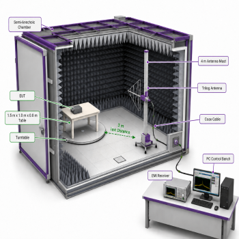
A typical Level 1 facility is a validated 3-meter or 10-meter semi-anechoic, fully anechoic, or open-area test site equipped with:
- A compliance-grade EMI receiver
- A calibrated measurement antenna
- A turntable
- An antenna mast capable of the required height scan, commonly from 1 to 4 meters
- Horizontal and vertical antenna polarization
- A characterized measurement path
- Validated site performance
- Documented measurement uncertainty
The exact facility and measurement configuration depend on the applicable product standard, regulatory requirement, frequency range, and EUT type.
Why the Turntable Is Important
The EUT rarely radiates equally in every direction. Rotating the EUT through 360 degrees allows the test system to identify the azimuth producing the maximum emission.
Without a turntable or equivalent azimuth search, the test may measure a repeatable signal while missing the actual maximum radiation direction.
Why the Antenna-Height Scan Is Important
Below approximately 1 GHz, the signal arriving at the antenna is influenced by both the direct radiation from the EUT and reflected energy from the ground plane. Depending on frequency, phase, antenna height, and EUT geometry, these signals can add or cancel.
Moving the antenna from 1 to 4 meters identifies the height at which the combined field is maximized.
A fixed-height antenna can therefore underestimate an emission, even when the receiver, antenna, and test distance are otherwise correct.
Measurement Confidence
Level 1 provides the highest confidence because the entire measurement chain and test site are evaluated against the applicable requirements. The result is suitable for formal compliance decisions when the facility, equipment, test method, and documentation meet the governing standard.
Even Level 1 measurements are not mathematically exact. They remain subject to measurement uncertainty, EUT variability, cable placement, operating-mode selection, and differences between laboratories. However, they provide the most standardized and directly comparable result.
Level 2: Three-Meter Compact Chamber with Turntable and Limited Antenna Height

A Level 2 system maintains the standard 3-meter separation between the EUT and antenna but uses a smaller chamber with a limited antenna mast, often fixed at or near 1 - 1.5 meter.
The system normally includes:
- A 3-meter measurement distance
- A turntable
- Horizontal and vertical antenna polarization
- A fixed or limited-height antenna position
- RF absorber around the measurement area
- An EMI receiver or spectrum analyzer
- Controlled cable routing and EUT configuration
Principal Benefits
Maintaining the 3-meter test distance is a major advantage because it reduces the need to mathematically convert a short-distance measurement to a 3-meter equivalent.
The turntable allows the engineer to search for the worst-case EUT azimuth. This makes Level 2 substantially more useful than a fixed EUT and fixed antenna arrangement.
A properly designed compact chamber also provides:
- Strong ambient-signal isolation
- Better measurement repeatability
- Faster testing
- A setup that can remain permanently configured
- Good comparison between design revisions
- A relatively strong relationship to the final 3-meter result
Primary Limitation
The principal limitation is the absence of a complete antenna-height search.
At some frequencies, the maximum emission may occur above the available antenna height. The Level 2 system may therefore identify the correct emission frequency and worst-case EUT orientation while underestimating the maximum amplitude.
Compact chamber dimensions and absorber depth may also affect performance at lower frequencies, where absorber efficiency is more difficult to achieve. The use of ferrite tiles with cone absorbers allows for low-frequency coverage.
Expected Correlation
Level 2 generally provides good correlation to final compliance testing when:
- The EUT fits comfortably within the chamber quiet zone
- The absorber is effective over the required frequency range
- The 3-meter geometry is maintained
- EUT and cable configurations are controlled
- Both polarizations are measured
- The EUT is rotated
- A product-specific correlation has been established
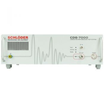
A Level 2 result should normally be evaluated with a conservative guard band. The required margin should be based on comparison testing between the compact chamber and the intended full-compliance facility. This can be achieved using a Comb Generator. It can be measured in the compliance chamber and the pre-compliance chamber to compare and determine the resulting difference.
Level 2 is appropriate for development and final engineering verification before the product is sent to an accredited or formal compliance laboratory.
Level 3: One-Meter Compact Chamber with Turntable

A Level 3 system reduces the measurement distance to approximately 1 meter while retaining a shielded and absorber-lined environment and an EUT turntable.
This configuration is smaller, less expensive, and easier to install than a 3-meter chamber.
Principal Benefits
The shorter test distance increases the received signal level. Under ideal far-field conditions, reducing the distance from 3 meters to 1 meter produces an approximate increase of:
20 log10(3/1) = 9.54 dB
This stronger signal can improve the measurement system’s effective sensitivity and make low-level emissions easier to observe.
Additional benefits include:
- Smaller chamber footprint
- Lower absorber and shielding cost
- Faster EUT access
- Strong ambient isolation
- Good measurement repeatability
- Turntable-controlled azimuth search
- Permanent and repeatable cable placement
- Effective comparison of design revisions
Limitations of One-Meter Measurements
The theoretical 9.54 dB distance conversion assumes conditions that may not exist in a compact chamber.
At 1 meter, the antenna may be in the radiating near-field or reactive near-field of part of the EUT, particularly when:
- The EUT is physically large
- Long cables or harnesses are present
- The frequency is relatively low
- Multiple radiating structures contribute to the measured field
- The EUT has a complex radiation pattern
Consequently, a simple 9.54 dB subtraction does not guarantee an accurate 3-meter equivalent.
The shorter distance also increases sensitivity to relatively small changes in:
- Antenna position
- Cable routing
- EUT orientation
- Chamber reflections
- Probe-to-source geometry
- The physical position of individual circuit boards or openings
Expected Correlation
Level 3 usually identifies the important emission frequencies and shows whether a design change improves or worsens performance.
Amplitude correlation to a 3-meter or 10-meter full-compliance facility is less direct than Level 2. However, useful product-specific correlation can be established by measuring the same representative EUT in both facilities. In this case, a Comb Generator can be used for a good comparison, and a correction factor could be created.
Level 3 is particularly effective when the objective is:
- Design comparison
- Margin tracking
- Emissions trend analysis
- Software-mode comparison
- Cable and enclosure evaluation
- Verification of corrective actions
It should not be treated as a direct compliance result unless the applicable standard specifically permits the method and the facility has been validated accordingly.
Level 3.5: GTEM Evaluation

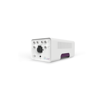
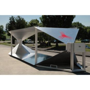
A level 3.5 system uses a gigahertz transverse electromagnetic cell (GTEM), fits between the compact-chamber and shielded-room approaches. This is an in-between level that is better than just a shielded room but slightly less than the 1-meter chamber. It fits within level 3 but does have some additional drawbacks.
A GTEM is a closed TEM waveguide that provides a controlled electromagnetic environment. IEC 61000-4-20 addresses emissions and immunity test methods using TEM waveguides, including closed structures such as TEM cells. It also addresses TEM-waveguide characteristics, EUT-size limitations, validation, and test procedures.
Principal Benefits
A GTEM offers several important advantages:
- Excellent ambient-signal isolation
- High measurement repeatability
- Broadband operation
- No separate measurement antenna
- No conventional antenna mast
- Compact footprint compared with a 3-meter chamber
- Fast testing
- Suitability for emissions and immunity work
- Good production-screening capability
Because the EUT remains in a controlled structure, GTEM measurements can be more repeatable than measurements in a minimally treated shield room or EMI tent.
Multiple EUT Orientations Are Necessary
A GTEM does not observe the EUT in the same way as an antenna positioned several meters away.
The measured signal depends strongly on the orientation of the EUT relative to the GTEM septum and electromagnetic field. A single EUT orientation is generally insufficient to characterize the total radiation.
Multiple orthogonal orientations (X, Y, & Z) are specified in the IEC 61000-4-20 standard, along with a complex derivative equation used to derive the measurement. and are required to estimate the EUT’s equivalent radiated behavior. Or, to have an easier, more comparable result, H & V measurements are simulated by turning the EUT 90 on its side. Cable orientation and placement are also critical.
EUT Size
The EUT must be appropriately sized relative to the usable test volume of the GTEM. A large EUT can significantly disturb the field or come too close to the septum. A rule of thumb is that 1/3 of the distance is allowed. GTEMs come in many sizes and are ideally suited for smaller EUTs. Larger EUTs make the GTEM larger and larger, making a compact chamber increasingly desirable.
Expected Correlation
GTEM testing can provide very good repeatability and useful correlation when:
- The EUT is small relative to the test volume
- Multiple orientations are measured
- Cable placement is tightly controlled
- The applicable conversion method is followed
- Product-specific correlation data are available
However, there is no universal GTEM correction factor that will accurately predict every 3-meter or 10-meter chamber result.
A GTEM is particularly effective for:
- Design comparison
- Product-family evaluation
- Production screening
- Firmware-mode testing
- Corrective-action verification
- Small-product development
- Repeated measurements requiring high consistency
Level 4: Shielded Room or EMI Tent

A Level 4 facility uses a shielded room or conductive EMI tent large enough to establish a 3-meter or 1-meter measurement distance.
A turntable may be installed, and absorber may be placed strategically around the EUT, antenna, walls, or floor.
Shielding Does Not Equal Absorption
A shielded room or EMI tent reduces external RF signals. It does not automatically provide a reflection-free environment.
Conductive walls reflect electromagnetic energy. The antenna can therefore receive:
- Direct radiation from the EUT
- Reflections from the floor
- Reflections from the ceiling
- Reflections from the sidewalls
- Multiple delayed reflections
- Signals coupled from cables and room penetrations
These reflections produce standing waves, constructive interference, and destructive interference.
At one frequency, a reflection may increase the measured signal. At another frequency, it may cancel part of the direct signal and make the EUT appear quieter than it would be in the final chamber.
Benefits
Despite these limitations, a shielded room or EMI tent can be extremely useful for engineering work. The use of a tent allows for the structure not to be permanent. Taking roughly a ½ day to assemble and take down.
Benefits include:
- Reduction of ambient broadcast, cellular, Wi-Fi, and other RF signals
- Controlled test access
- Permanent or repeatable equipment placement
- Compatibility with larger EUTs
- Lower cost than a fully absorber-lined chamber
- Ability to use a turntable
- Support for 1-meter or 3-meter testing
- Effective design-to-design comparison
Strategically placed absorber can reduce the strongest reflections and improve correlation. The absorber placement should remain fixed once a correlation baseline has been established.
Expected Correlation
Level 4 measurements can be highly repeatable within the same room while having limited absolute correlation to a full-compliance result.
The use of a 3-meter distance does not, by itself, make the test equivalent to a compliant 3-meter chamber. Reflections, antenna-height limitations, room dimensions, and unvalidated site attenuation remain significant.
Level 4 is best used for:
- Comparative measurements
- Gross emissions screening
- Identification of high-risk frequencies
- Verification that a corrective action produced a substantial improvement
- Large-EUT evaluations that cannot fit into a compact chamber
- Internal acceptance limits based on a characterized reference product
When possible, the same known EUT should be measured in the shielded room and in a full-compliance chamber. The observed frequency-dependent differences can then be used to establish an internal engineering guard band.
Level 5: Benchtop Near-Field Probing and Scanning

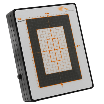
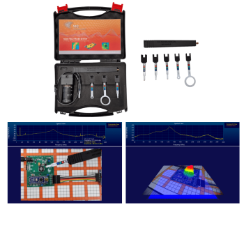
Level 5 is a benchtop development and troubleshooting method using electric-field probes, magnetic-field probes, current probes, and automated or manual scanning systems.
Level 5 does not attempt to reproduce the final 3-meter or 10-meter electric-field measurement. Instead, it identifies where the emissions originate and how they are coupled into radiating structures.
Near-field scanning is recognized as a diagnostic method in applications such as integrated-circuit evaluation. For example, IEC TS 61967-3 defines procedures for evaluating near electric, magnetic, or electromagnetic fields at or near the surface of an integrated circuit.
What Level 5 Can Identify
Near-field measurements can locate emissions associated with:
- Clock oscillators
- Switching power supplies
- DC-to-DC converters
- Microprocessors
- Memory buses
- High-speed serial interfaces
- Connector transitions
- Common-mode currents
- Cable shields
- Enclosure seams
- Display interfaces
- Poor PCB return paths
- Unfiltered I/O lines
Magnetic-field probes are especially useful for identifying current loops and high-frequency currents. Electric-field probes can help identify high-impedance nodes, voltage-driven coupling, and fields around connectors, cables, and enclosure openings.
Why Level 5 Does Not Directly Predict Compliance
Near-field probes measure fields very close to the source. At these distances, the electric and magnetic fields do not necessarily have the free-space relationship present in a propagating far-field wave.
Probe output is affected by:
- Probe type and orientation
- Probe distance
- Probe loading
- Scan height
- Spatial resolution
- Cable movement
- Preamplifier gain
- Probe calibration
- Local source impedance
- Coupling to adjacent structures
A signal that appears very strong with a near-field probe may couple poorly into the final radiating structure. Conversely, a relatively small PCB-level signal may drive a long cable or enclosure resonance and produce a significant far-field emission.
For this reason, Level 5 results should not normally be expressed as a direct pass/fail comparison to a regulatory field-strength limit.
Essential Role in Development
Level 5 should not be considered the least valuable testing level. It answers a different and often more important engineering question:
Where is the emission coming from, and what must be changed to reduce it?
Full-compliance testing may identify a failure at 180 MHz. A near-field scan can determine whether the 180 MHz signal originates from a clock harmonic, an Ethernet interface, a switching regulator, a cable common-mode current, or an enclosure seam.
Level 5 is essential for:
- Early product development
- PCB layout evaluation
- Component selection
- Filter evaluation
- Shielding development
- Cable and connector troubleshooting
- Root-cause analysis following a Level 1 failure
- Verification that a proposed corrective action attacks the actual source
Level 5 testing helps a product pass Level 1, and it provides the tools needed to correct the product when a Level 1 failure occurs.
The Effect of Using a Compliance-Grade Receiver at Lower Levels
Using the same compliance-grade EMI receiver at Levels 2, 3, 3.5, or 4 provides significant benefits.
CISPR 16-1-1 specifies performance requirements for EMI receivers and spectrum analyzers used to measure radio disturbances, including equipment operating over the 9 kHz to 18 GHz range.
A compliance-grade receiver provides:
- Correct resolution bandwidths
- Standardized peak, quasi-peak, average, or RMS-average detector behavior
- Better dynamic range
- Better overload protection and indication
- Calibrated amplitude performance
- Repeatable dwell and measurement timing
- Reliable frequency accuracy
- Automated correction-factor support
- Easier transfer of test settings to the final laboratory
However, the receiver is only one part of the measurement system. All other aspects of the test setup need to be maintained and reproduced each time.
A compliance receiver cannot correct for:
- Chamber reflections
- Missing antenna-height maxima
- Near-field conditions
- Inadequate test distance
- Incorrect cable placement
- Incomplete EUT rotation
- Poor absorber performance
- EUT orientation differences
- An unvalidated measurement site
It is therefore more accurate to state that a compliance-grade receiver reduces instrument-related uncertainty and generally improves measurement precision and repeatability. It does not make a noncompliant facility equivalent to a validated compliance site.
Using the same receiver, bandwidths, detectors, transducers, correction factors, and measurement software at every level can nevertheless improve consistency between development and final testing.
Establishing Correlation Between Testing Levels
The most effective pre-compliance system is not necessarily the most expensive system. It is the system whose relationship to the final compliance result is understood.
A correlation program should use one or more representative “golden” EUTs. Or, easier to use, is a Comb Generator, as it produces a wide spectrum of frequencies, not just a few emitting frequencies. This allows better coverage and to see how the facility reacts across the whole testing band. That said, a representative golden EUT of size and cabling does have strong benefits as well.
Each golden EUT should be measured at the available pre-compliance level and at the intended full-compliance facility using the same:
- Operating mode
- Software revision
- Cable set
- Cable length
- Peripheral equipment
- Power configuration
- Grounding arrangement
- Load condition
- Antenna polarization
- EUT orientation references
The comparison should be made frequency by frequency. A single overall correction factor is not adequate because chamber and setup differences normally vary across the spectrum. Frequency is a dimension.
The correlation record should identify:
- Frequencies that correlate closely
- Frequencies consistently overestimated
- Frequencies consistently underestimated
- Sensitivity to antenna height
- Sensitivity to cable position
- Sensitivity to EUT azimuth
- Required engineering guard band
This creates an internal measurement history that is much more valuable than relying on a generic claim that a particular type of chamber is accurate within a fixed number of decibels.
Recommended Development Workflow
The levels work best when they are used together rather than treated as competing alternatives.
Early Development: Level 5
Use near-field probes and scanning to identify major noise sources before the mechanical design is finalized.
Correct PCB current loops, common-mode coupling, filtering, grounding, shielding, and cable-interface problems while changes are still inexpensive.
Prototype Integration: Levels 3, 3.5, or 4
Measure the assembled product in a repeatable controlled environment.
Identify critical frequencies, evaluate cable configurations, compare enclosure options, and establish internal margin targets.
Pre-Compliance Verification: Level 2
Test the final or near-final product at a 3-meter distance with EUT rotation, both antenna polarizations, and compliance receiver settings.
Apply an established guard band to account for the limited antenna-height search and compact chamber characteristics.
If a Level 2 chamber is not available, an open area or office can be used to get the correct test distance with the emissions antenna. Because of the work performed in the other levels (5, 4, or 3), you know which frequencies to focus on and ignore the other ambient signals. This can provide the same correlation for understanding how close you are to the standard levels. This is an ideal use to know before you go to the lab to have more confidence in your design.
Final Qualification: Level 1
Perform the complete required test using the specified detector, bandwidth, test distance, antenna-height search, EUT rotation, cable configuration, operating modes, and validated test site.
If the product fails, return to Level 5 to locate the source and then use Levels 3 or 2 to verify the correction before repeating Level 1.
Conclusion
Radiated emissions testing is most effective when it is treated as a graduated engineering process.
Level 1 provides the formal compliance determination. Level 2 provides high-confidence 3-meter pre-compliance screening. Level 3 provides compact and repeatable product-level evaluation. Level 3.5 provides controlled GTEM testing with strong repeatability. Level 4 provides economical comparative testing for products that require a larger shielded area. Level 5 provides the diagnostic capability needed to identify and correct the actual emissions source.
No lower-level system can reproduce every aspect of a validated full-compliance facility. However, a well-controlled pre-compliance setup can dramatically reduce risk when its limitations are understood and its results have been correlated to Level 1 testing.
The objective is not to make every development measurement identical to the final compliance measurement. The objective is to obtain enough reliable information, early enough in the development process, to prevent expensive failures at the end.
All product development should include level 5 tools as a minimum. These are used in conjunction with the other levels and are absolutely required to develop products that are destined for RE testing.