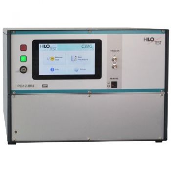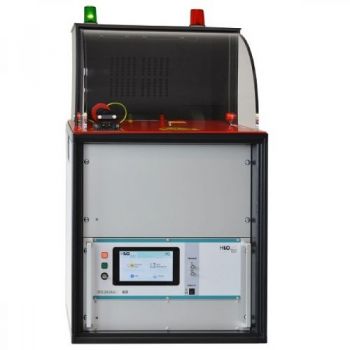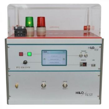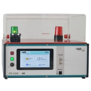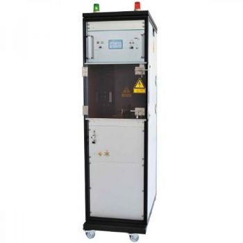
PG 20-10000 Surge Current Generator 70kA
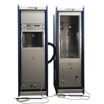
The surge current generators PG20-10k generates standard impulse currents with waveform 8/20 µs according to IEC, EN, VDE. Pulse current output amplitude is controlled by preset charging voltage and can be adjusted up to 70 kA. The generator is designed for testing electrical components, over-voltage protectors and surge protection devices. The generator possesses an electronically regulated high-voltage power supply, which allows an excellent reproducibility of the pulse output amplitude.
Surge Current Generators
PG 20-10000
-
Waveform 8/20 µs +/-10%
-
Surge current amplitude: up to 70 kA
-
acc. Standard IEC 61643-11
pulse current test of surge protection devices
The surge current generators PG20-10k generates standard impulse currents with waveform 8/20 µs according to IEC, EN, VDE. Pulse current output amplitude is controlled by preset charging voltage and can be adjusted up to 70 kA.
The generator is designed for testing electrical components, over-voltage protectors and surge protection devices. The generator possesses an electronically regulated high-voltage power supply, which allows an excellent reproducibility of the pulse output amplitude.
The pulse-forming network contains a pulse-fidelity current viewing resistor for monitoring the output waveform. The impulse current output is located at the top of the equipment and provides high-current bolts M12 with a changing test adapter M12.
The generator features a microprocessor-controlled user interface and display unit for ease of use. The microprocessor allows the user to either execute standard test routines, or a ´user-defined´ test sequence. The test parameters, which are shown on the built-in display, are easily adjusted by means of the rotary encoder. A standard parallel interface provides the ability to print a summary of the test parameters whilst testing is being carried out.
|
TECHNICAL SPECIFICATIONS |
PG 20-10k |
|
|
|
|
Control unit: |
|
|
Microprocessor controlled LCD module |
8*40 characters |
|
Parallel printer interface for on-line documentation |
25-way ´D´ connector |
|
Optical-interface for remote control of the generator |
built-in |
|
External Trigger input |
10 V at 1 kW |
|
External Trigger output |
10 V at 1 kW |
|
Diagnostic input for monitoring of the test device |
4 channels, 5 V - Level |
|
Mains supply voltage |
230V / 50-60 Hz |
|
Build in 19”-cabinet |
|
|
Internal red and green warning lights according to VDE 0104 |
220V/60W |
|
|
|
|
Pulse generator section: |
|
|
Peak value of charging voltage, adjustable, |
0 - 20 kV, ± 2% |
|
Max. stored energy |
10 000 Ws |
|
Charging time for max. charging voltage |
< 80 sec |
|
|
|
|
Waveform of impulse output current |
8 / 20 µs ± 10 % |
|
Impulse output current, adjustable via charging voltage |
5 - 70 kA ± 10 % |
|
|
|
|
Pulse repetition rate for 70kA |
1/83 sec |
|
Pulse repetition rate for 40kA |
1/47 sec |
|
Output pulse polarity, switchable |
POS/NEG/ALT |
|
Current viewing resistor, built-in |
0.25 mW, 10 MHz |
|
|
|
|
Impulse current output terminals: in the test chamber |
M12 bolts |
|
test adapter on the output terminals |
M12 bolts |
|
Ground rod |
0,6 m |
|
|
|
|
Dimensions: 19"-cabinet W * H * D |
ca. 560*1950*950 mm3 |
|
Weight |
200 kg |
|
|
|
|
OPTION 1: Remote control PC Software Incl. 5 m long fibre optic cable and USB-PC Interface ( XP, WIN7 ) |
|
|
|
|
|
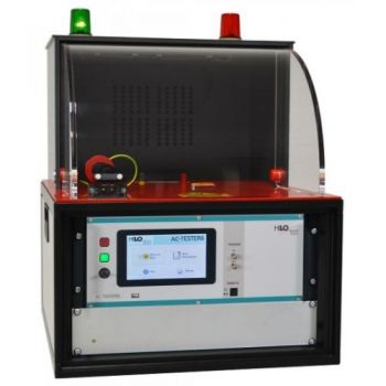
OPTION 2: Test chamber on top, build in 19” rack, with security glass door, safety interlock protects the high-voltage output terminals. Upon opening of the door, switching-off of the generator or mains blackout a built-in high-voltage grounding switch, discharges the test object and the internal energy storage capacitor. Test space ca. W*H*D 470*530*490 mm³ |
|
|
|
|
|
OPTION 3: Current impulse triggering synchronization 0-360° to the zero crossing of the sinusoidal mains voltage, phase angle in steps of 1°. Mains power (E.U.T. power supply) 400Veff / 50Hz Without decoupling from HV – power supply. |
|
|
|
|
|
OPTION 4: Galvanic isolated measurement of current impulse with a Pierson coil. |
|
|
|
|
|
OPTION 5: Polycarbonate security door with solid hinges and fasteners made of stainless steel. |
|


