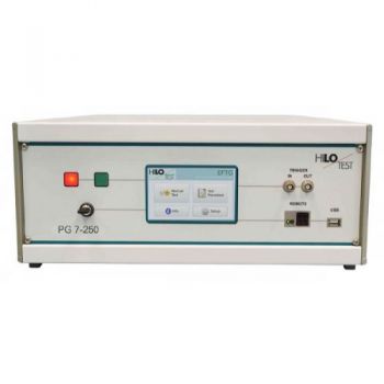
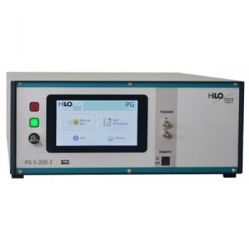
PG 6 250: VARISTOR TESTER
The VARISTOR-TESTER PG 6-250 is a compact test generator for testing the surge current capability of varistors. The unit contains a combination wave generator and a surge voltage generator acc. to CCITT, ITU-T.
PARTNER:
MARKETS:
CATEGORIES:
TEST STANDARDS:

Data Sheet
SPECIFICATIONS
VARISTOR-TESTER PG 6-250
Combination wave generator:
· Surge voltage:
o 1.2/50µs, 6 kV Surge current:
o 8 / 20 µs, 2.4 kA
· + Surge voltage 10 / 700 µs
o acc. to CCITT, ITU - T
The VARISTOR-TESTER PG 6-250 is a compact test generator for testing the surge current capability of varistors. The unit contains a combination wave generator and a surge voltage generator acc. to CCITT, ITU-T.
The surge voltage generator delivers standard impulse voltages with the waveform 10/700µs. The pulse output amplitude can be adjusted up to 4.8 kV.
The combination wave generator integrated, delivers a standard impulse voltage with waveform 1.2/50 µs for high-impedance loads, RL > 100W, and delivers a standard impulse current with waveform 8/20 µs for short-circuited output. The peak value of the impulse output voltage can be adjusted up to 6.3 kV.
In order to test different types of varistors, the pulse forming network can be switched to three different ranges, surge currents from 1 A up to 2.4 kA can be generated.
The VARISTOR-TESTER, PG 6-250, features a microprocessor controlled user interface and display unit for ease of use. The microprocessor allows the user to either execute standard test routines or a ´user-defined´ test sequence. The test parameters, which are shown on the built-in display, are easily adjusted by means of the rotary encoder. A standard parallel interface provides the ability to print a summary of the test parameters whilst testing is being carried out. Moreover, all generator functions may be computer controlled via the isolated optical interface.
PG 6-250 is able to generate the specified pulse current amplitudes even if the test device is connected to the output. Regarding the current range for surge testing, the varistor can be described by a voltage source Vz in series with a variable resistor Rdyn. The series impedance and a clamping voltage of test device influence the pulse current amplitude. The maximum pulse current amplitudes with a varistor, Vz = 500V, Rdyn = 2.5-250 W, connected are noted in the data sheet. The software for remote control is able to calculate the parameter setting of the generator, depending on technical data of the varistor. Using the PU 10 switch unit allows successive testing of up to 10 devices, located on a PCB.
|
Technical specification |
PG 6-250 |
|
Main frame: |
|
|
Microprocessor controlled LCD module |
8*40 characters |
|
Parallel printer interface for online documentation |
25-way ´D´ connector |
|
Optical-interface for remote control of the generator |
built-in |
|
external trigger input: trigger-delay < 10µs |
10 V and 1 kW |
|
4 diagnosis inputs for monitoring of the test device |
10 V and 1 kW |
|
Connector for external safety interlock loop |
24 V = |
|
and external red and green warning lamps acc. to VDE 0104 |
230 V, 60W |
|
Mains power |
230 V, 50/60 Hz |
|
Dimensions: desktop case W * H * D |
471*180*410 mm3 |
|
Weight |
28 kg |
|
|
|
|
Pulse forming network: |
switchable |
|
a) Combination wave generator |
1.2 / 50 µs, 8/20µs |
|
voltage wave, open circuit condition: front-time / tail-time |
8 / 20µs±20% |
|
charging voltage Vo, adjustable in steps of 25V |
200 V - 6375 V ± 5% |
|
current wave: front-time / tail-time |
8 / 20µs±20% |
|
pulse current amplitude, adjustable, via charging voltage available: |
Vo - Vz |
|
a1 PFN 1: pulse current amplitude: short circuit / Rdyn < 2.5W |
2.4 kA / 1.2 kA |
|
a2 PFN 2: pulse current amplitude: short circuit / Rdyn < 25W |
180 A / 100 A |
|
a3 PFN 3: pulse current amplitude: short circuit / Rdyn < 250W |
16 A / 10 A |
|
|
|
|
b) Surge voltage with waveform 10/700µs acc. to CITT K17/K22, IEC 1000-4-5 |
|
|
charging voltage Vo, adjustable in steps of 25V |
200 V - 5000 V ± 5% |
|
energy storage capacitor |
20µF/5.0 kV |
|
max. energy stored |
200 J |
|
discharging resistor |
50 W |
|
series resistor |
15 W |
|
load capacitor |
0.2 µF |
|
damping resistor to the output terminal |
25 W |
|
waveform: front-time / tail-time |
10/700µs ± 20% |
|
|
|
|
pulse output polarity, selectable |
pos/neg/alt |
|
charging time |
< 10 sec |
|
pulse output connector |
coaxial |
|
Monitor output for pulse output voltage |
ratio=100:1 ± 2%, 500W |
|
Monitor output for pulse output current, switchable, Rm |
10/100/1000 mW ± 2% |
|
Option 1: Software PG 6-250, for remote control incl. 5 m fiber-optic cable and PC-interface |
|
|
Option 2: Peak detector, built-in, Display of peak values of voltage and current. |
|
|
Option 3: Control and connectors for Load Damp Generator 2803 |
|
|
Option 4: Customer specific fixture on PU 10 for test samples |
|
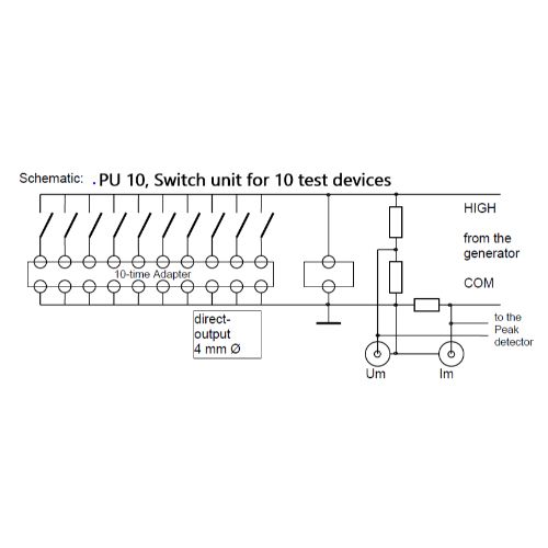
Test device switch unit PU 10
built-in under the safety test cover mounted on the test table.
· Switch unit for 10 test devices
· maximum test current: 1.2 kA, 8/20µs
· Adapter for test board, connected by contact pins.
· Impulse voltage divider integrated, BNC output for measuring the residual voltage of the test device with an external scope.
· Impulse current measuring resistor with BNC-output for external measurement.
· Impulse current measuring resistor connected to the internal peak detector, display of peak values, in conjunction with Option 2.
· Impulse voltage divider connected to the internal peak detector. Display of peak values, in conjunction with Option 2.
· Direct pulse output for testing single components, 4 mm Ø connectors.
Schematic: See Image above
· The complete unit can be simply replaced, if the contact pins are damaged.
|
Technical specification |
PU 10 |
|
|
|
|
Attention! Monitor output specification above is replaced by the following specification: |
|
|
Impulse voltage divider, built-in |
100:1 ± 2%, B = 100 kHz |
|
Monitor output for external scope |
BNC |
|
Impulse current shunt, switchable: |
|
|
PFN 1 |
2 kA 10 mW, ±2%, 100 kHz |
|
PFN 2 |
200 A 100 mW, ±2%, 100 kHz |
|
PFN 3 |
20A 1.0 W, ±2%, 100 kHz |
|
Monitor output for external scope |
BNC |
|
Accuracy of the internal peak detector |
± 5% / full scale |
|
incl. safety test cover mounted on the test table |
|
|
|
|
OTHER PRODUCTS IN THE SAME CATEGORY:

HTS 20-10, 20 kV, DC dielectric strength

IPG 1201, Insulation Tester, 12kV

IPG 2025 / IPG 2436, Impulse Wave Generator 20kV or 24kV
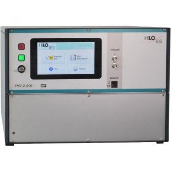
PG 12-400, 12kV, Impulse Wave Generator

IPG 1218 / 1012 / 605, Insulation Test, 12kV, 10kV, 6.25kV

IPG 255, Insulation Tester, 8kV
PG 24 - 2500 Surge Test Generator
AC-Tester 6, 10 kV Alternating voltage, Isolation testing set
PG 20 - 4000, High Voltage Pulse Generator, 10/700µs, 5/320µs, 20kV
PG 14 - 1960, High Voltage Pulse Generator, 10/700µs, 0.5/700µs, 14kV
PG 12 - 1440, High Voltage Pulse Generator, 10/700µs, 1.2/50µs, 12kV
PG 5-200 / PG 10-1000, High Voltage Pulse Generator, 10/700µs, 5/350µs, 1.2/50µs

PG 20-100 Solar modules test, 20kV
PG 10-200 / PG 12-360, Solar modules test, 10kV & 12kV
PG 10-150, Flammability test, 10kV

IPG 809, Capacitor Tester, 8kV
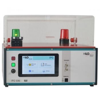
IPG 506: FRONT-CHOPPED-WAVE GENERATOR
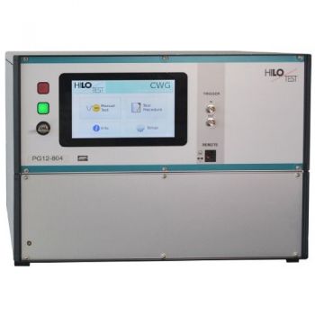
PG 12-804 12kV Surge CWG
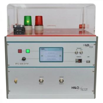
IPG 506 SYM: FRONT-CHOPPED-WAVE, 3-Pole DUT

