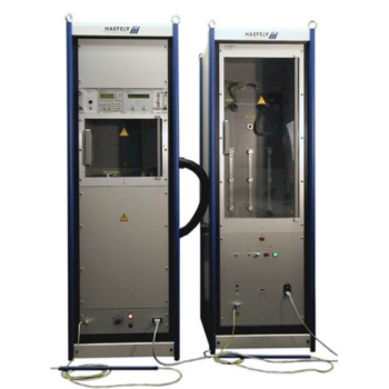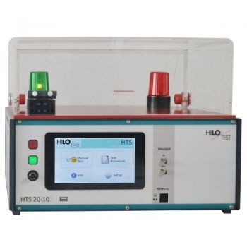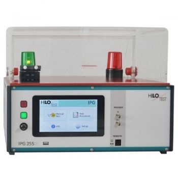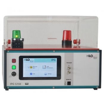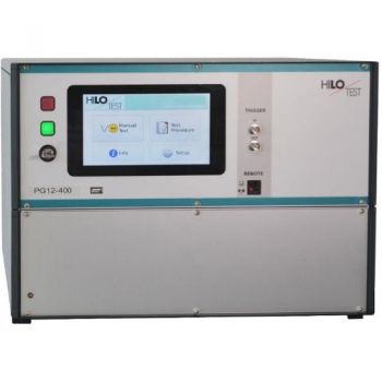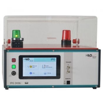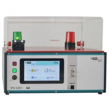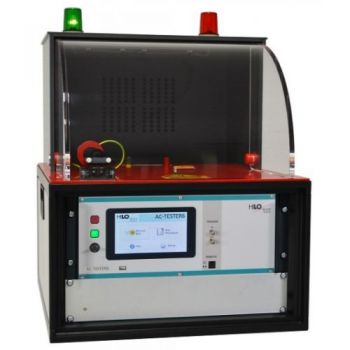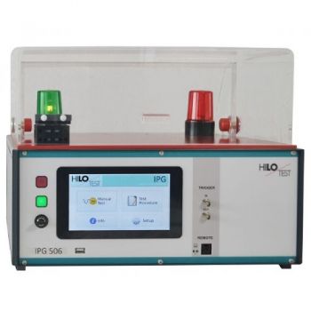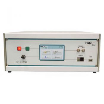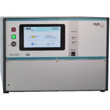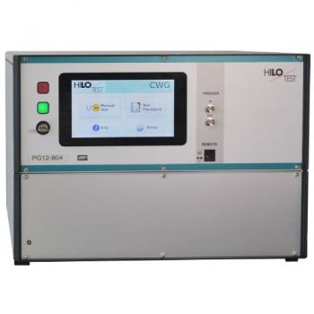
PG 10-200 / PG 12-360, Solar modules test, 10kV & 12kV
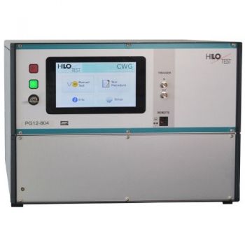
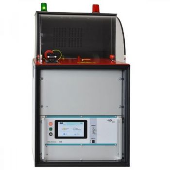
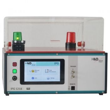
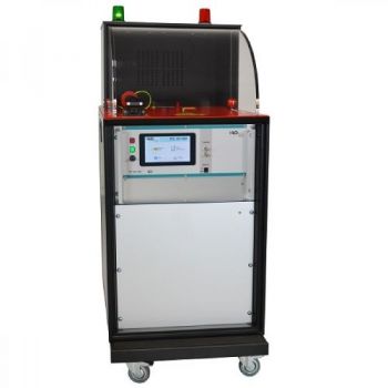
The HV-Pulse generator PG10-200 / PG12-360 is used for impulse voltage tests of solar modules (photovoltaic panels) with the standard surge voltage waveform 1.2/50 µs according to IEC 60060-1/2 up to 10 kV acc. to. IEC 61730-1/2 / EN 61730-1. For the surge voltage tests of solar modules, these are enveloped with a copper foil as described in the relative above standard. After that the connections of the solar modules are tested with surge voltage against the copper foils. The tight copper foil envelope required by the standard results in comparatively high capacitances of approx. 0 - 183 nF, which is switched in parallel to the output of the impulse generator.
PG 10-200 / PG 12-360
| |
Impulse voltage tests of Solar Modules
| |
|
Generator |
PG 10-200 |
PG 12-360 |
|
Surge voltage 1.2 / 50 µs |
0.5 – 10 kV |
1.0 – 12 kV |
|
Capacitors |
0 nF – 183 nF |
|
| |
|
According to |
|
IEC 61730 – 1/2 |
| |
The HV-Pulse generator PG10-200 / PG12-360 is used for impulse voltage tests of solar modules (photovoltaic panels) with the standard surge voltage waveform 1.2/50 µs according to IEC 60060-1/2 up to 10 kV acc. to. IEC 61730-1/2 / EN 61730-1.
For the surge voltage tests of solar modules, these are enveloped with a copper foil as described in the relative above standard. After that, the connections of the solar modules are tested with surge voltage against the copper foils. The tight copper foil envelope required by the standard results in comparatively high capacitances of approx. 0 - 183 nF, which is switched in parallel to the output of the impulse generator.
Therefore, a special impulse voltage generator is required for this standard specified test, which can generate the specified impulse wave shapes for the different EUT-capacitances, which are a result of the varying dimension of the solar modules to be tested.
The high voltage Pulse Generator comprises 8 different pulse forming networks, which allow generating the requested wave shapes fully complying with the tolerances specified in the standard for the different EUT capacitances.
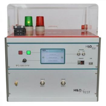
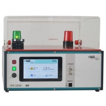
The PG10-200 / 12-360 excels by its compact design, simple handling and precise reproducibility of test impulses. The output current- and voltage waveforms, due to built-in sensors, can be recorded via separate signal outputs for current and voltage.
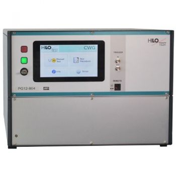
The generator features a microprocessor-controlled user interface and a 7” touch screen unit for ease of use. The microprocessor allows the user to execute either standard test routines or a “user-defined” test sequence. The test parameters which are shown on the built-in display, are easily adjusted by means of a touch screen.
A standard USB port provides the ability to print a summary of the test parameters to a USB stick.
Moreover, all generator functions may be computer-controlled.
The software program PG-REMOTE allows full remote control of the test generator via fiber optic Ethernet interface as well as documentation and evaluation of test results, according to the IEC 17025. To record definite impulses, it is equipped with an Impulse Recording Function (IRF)
|
|
|
Options |
PG 10-504 PG 12-804 |
|
|
|
|
PC software for remote control |
PG-REMOTE |
|
PG Remote software test package, running under Microsoft Windows, for the external control of the device |
|
|
( XP, WIN7, WIN10 ) includes 5 m long fiber optic cable and Ethernet PC Interface |
|
|
|
|
|
CAPACITOR-CALIBRATION-KIT |
CCK |
|
27nF,45nF,68nF,113nF ± 3% |
|
| |
|
TECHNICAL SPECIFICATIONS |
|
PG 10-504 |
PG 12-804 |
|
|
|
||||
|
Mainframe |
||||
|
Microprocessor controlled touch panel |
|
7”, capacitive |
||
|
Optical Ethernet Interface for remote control of the generator |
optional |
|||
|
Interface for saving reports |
|
USB |
||
|
External Trigger input / output |
|
Switch / 10 V |
||
|
Connector for external safety interlock loop |
24 V = |
|||
|
and external red and green warning lamps acc. to VDE 0104 |
230 V, 60W |
|||
|
Mains power |
|
230V, 50/60 Hz |
||
|
Dimensions: desktop case W * H * D |
|
450*330*500 mm3 |
||
|
Weight |
|
|
22 kg |
|
|
|
||||
|
High- Voltage Pulse Generator: |
||||
|
Impulse output voltage, adjustable ± 5% |
0.5 - 10 kV |
1.0 – 12 kV |
||
|
Waveform of Impulse output voltage |
||||
|
risetime |
|
|
1.2 µs ± 30% |
|
|
backtime |
|
|
50 µs ± 20% |
|
|
Polarity, selectable |
|
pos./neg. |
||
|
Maximum stored energy Cs |
|
250 J |
360J |
|
|
Charging time for max. charging voltage |
approx. 10sec |
|||
|
Interior load capacitance Cp |
|
10 nF ± 10% |
||
|
|
||||
|
Pulse forming networks to test solar modules: |
Cp = 0 - 183nF |
|||
|
selectable |
||||
|
Area |
EUT capacitances nominal |
range of EUT capacitances |
|
|
|
1 |
5nF |
0-10 nF |
|
|
|
2 |
15 nF |
10 - 16 nF |
|
|
|
3 |
22 nF |
16 - 27 nF |
|
|
|
4 |
33 nF |
27 - 40 nF |
|
|
|
5 |
47 nF |
40 - 57 nF |
|
|
|
6 |
68 nF |
57 - 83 nF |
|
|
|
7 |
100 nF |
84 - 122 nF |
|
|
|
8 |
150 nF |
123 - 183 nF |
|
|
|
|
||||
|
Spark-over detection: |
|
PASS / FAIL |
||
|
Impulse current output: on the generator’s rear panel |
HV female connector |
|||
|
Impulse high voltage dividers to observe the impulse wave shape built-in |
||||
|
ratio |
|
|
1000 : 1 ±2% |
|
|
|
||||
|
Accessories |
||||
|
mains cable, key, HV-connection cable, operation instructions |
||||
| |


