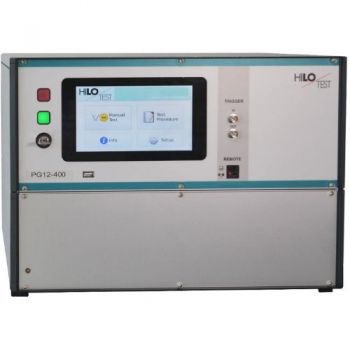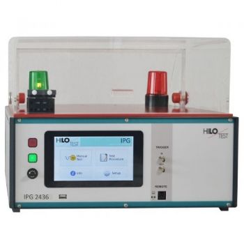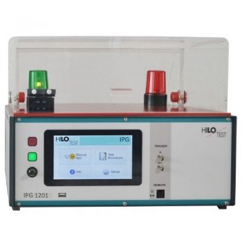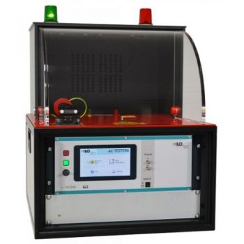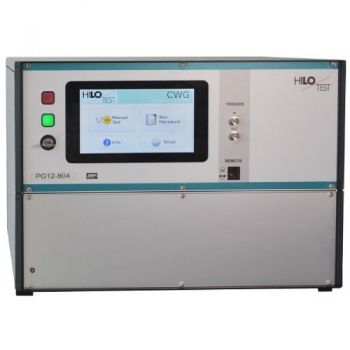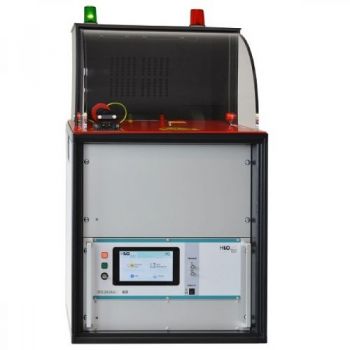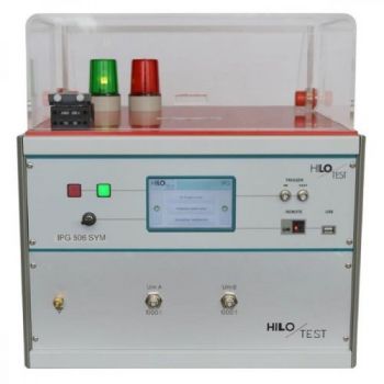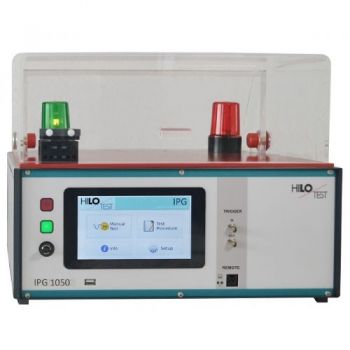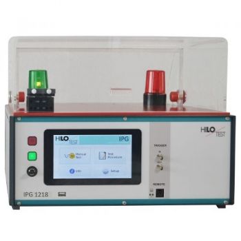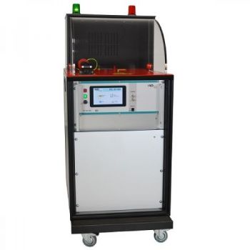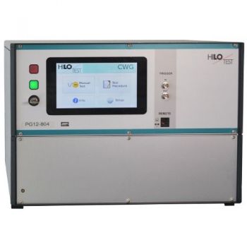
PG 12-804 12kV Surge CWG
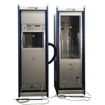
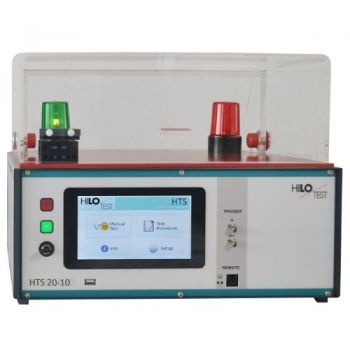
The Combination Wave Generator PG 12-804 is a combined impulse-current-/impulse-voltage generator which, for high-impedance loads, RL > 100?, delivers a standard impulse voltage with waveform 1.2/50µs and, for short-circuited output, a standard impulse current with waveform 8/20µs. The generator allows surge testing of components and devices, galvanic coupling of surges to cable shields, shielded enclosures and cabinets as well as testing electromagnetic compatibility, EMC, of electronic devices and systems against pulsed and conducted interference.
PARTNER:
MARKETS:
TEST STANDARDS:
PG 12-804
Combination Wave Generator
|
Generator |
PG 12-804 |
|
Surge voltage 1.2 / 50 µs |
0.2 – 12 kV |
|
Surge current 8 / 20 µs |
0.1 – 6kA |
|
According to |
|
IEC 61000-4-5 |
|
IEEE 587 |
The Combination Wave Generator PG 12-804 is a combined impulse-current-/impulse-voltage generator which, for high-impedance loads, RL > 100W, delivers a standard impulse voltage with waveform 1.2/50µs and, for short-circuited output, a standard impulse current with waveform 8/20µs.
The generator allows surge testing of components and devices, the galvanic coupling of surges to cable shields, shielded enclosures and cabinets as well as testing electromagnetic compatibility, EMC, of electronic devices and systems against pulsed and conducted interference.
Using an external Coupling-/Decoupling Network allows superimposition of the combination wave generator's output to the mains voltage of the device under test. The test set-up is suitable for surge immunity testing of electronic systems and devices full compliant to IEC 61000-4-5 and IEEE 587. Demonstrating such immunity is generally a requirement for compliance with the requirements of the European EMC directive, a necessary step leading to the final attachment of the CE mark.
Executing surge immunity tests at power supply a line triggering of high-voltage pulses is accomplished synchronous with mains. The precise trigger point can be shifted between 0 to
360 ° after the zero crossings of the mains voltage. The polarity of the output voltage is selectable. Positive, negative or alternating polarity of the output voltage can be preselected.
The PG 12-804 excels by its compact design, simple handling and precise reproducibility of test impulses. The output current- and voltage waveforms, due to built-in sensors, can be recorded via separate signal outputs for current and voltage.
The generator features a microprocessor controlled user interface and a 7” touch screen unit for ease of use. The microprocessor allows the user to execute either standard test routines or a “user-defined” test sequence. The test parameters which are shown on the built-in display, are easily adjusted by means of the touch screen.
A standard USB port provides the ability to print a summary of the test parameters to a USB stick.
Moreover, all generator functions may be computer controlled.
The software program PG-REMOTE allows full remote control of the test generator via fiber optic Ethernet interface as well as documentation and evaluation of test results, accordingly to the IEC 17025. To record definite impulses, it is equipped with an Impulse Recording Function (IRF)
|
TECHNICAL SPECIFICATIONS |
PG 12-804 |
|
|
|
|
Mainframe |
|
|
Microprocessor controlled touch panel |
7”, capacitive |
|
Optical Ethernet Interface for remote control of the generator |
optional |
|
Interface for saving reports |
USB |
|
External Trigger input / output |
switch/ 10 V |
|
Connector for external safety interlock loop |
24 V = |
|
and external red and green warning lamps acc. to VDE 0104 |
230 V, 60W |
|
Mains power |
90V - 264V, 50/60 Hz |
|
Dimensions: desk top case W * H * D |
450*330*500 mm3 |
|
Weight |
25 kg |
|
|
|
|
Combination Wave Generator acc. to IEC 61000-4-5: 2014 |
|
|
Test voltage, (open circuit condition) ± 10 % |
0.2 – 12 kV |
|
Waveform acc. to IEC 60060 |
1.2 / 50 µs ± 30/20 % |
|
Test current (short circuit condition) ± 10 % |
0.1 - 6.0 kA |
|
Waveform acc. to IEC 60060 |
8 / 20 µs ± 20 % |
|
Polarity of output voltage/current, selectable |
pos/neg/alt |
|
maximum stored energy |
800 Joule |
|
charging time for max. charging voltage |
< 20s |
|
HV-output: isolated from ground |
HV-OUT, COM |
|
|
|
|
Mains synchronous triggering : |
|
|
Phase shifting, digitally selectable |
0 - 360 °, Step 1° |
|
Ext.Sync. Input for synchronization to the external CDN mains |
built-in |
|
Optical output for control of external CDN |
built-in |
|
|
|
|
Display of peak values of pulse voltage and current |
built-in |
|
Monitor output for pulse output voltage |
ü = 1000 : 1 ± 5 % |
|
Monitor output for pulse output current |
10V º 5 kA ± 5 % |
|
|
|
|
Accessories |
|
|
power cable, turnkey, HV-cable, 1m, instruction manual |
|
|
Options |
PG 12-804 |
|
|
|
|
PC software for remote control |
PG-REMOTE |
|
PG Remote software test package, running under Microsoft Windows, for the external control of the device |
|
|
( XP, WIN7, WIN10 ) includes 5 m long fiber optic cable and Ethernet PC Interface |
|
|
|
|
|
Test cabinet |
PA 503, PA 505 |
|
Test adapter with safety cabinet for component testing |
|
|
|
|
|
Coupling/decoupling networks |
CDN 12416 |
|
Coupling/decoupling networks for immunity test |
|


