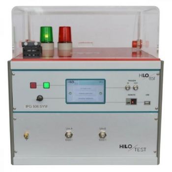
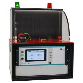
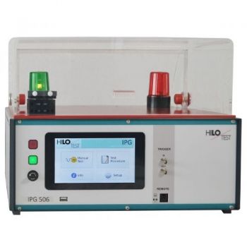
IPG 506 SYM: FRONT-CHOPPED-WAVE, 3-Pole DUT
The front-chopped-wave generator IPG 506 is used for measuring dc spark-over voltage and impulse spark-over voltage of over-voltage protectors according to CCITT / ITU-T, K12. DC spark-over voltage: A linearly rising voltage, rate of rise 100 V/s up to 640 V, simultaneous plus and minus, is connected to the device under test. The spark-over voltage of these two simultaneous impulses is measured and shown in the display. Impulse spark-over voltage: A linearly rising impulse voltage, simultaneous plus, and minus, rate of rise 100 V/µs up to 5000 V/µs, open loop amplitude 5000 V, is connected to the device under test. The spark-over voltage is measured by use of a peak detector. The results of these two simultaneous impulses are shown on the display. The picture is shown with PA 503 Option.
PARTNER:
MARKETS:
CATEGORIES:
TEST STANDARDS:

Data Sheet
SPECIFICATIONS
IPG 506 SYM: FRONT-CHOPPED-WAVE GENERATOR
Measurement of
DC spark-over voltage and impulse spark-over voltage
for 3-Pole Gas Discharge Tubes
Rise of output voltage, selectable:
600 V= : 100 V/s
5 kV impulse: 100V/µs - 5000 V/µs Insulation resistance 0.5kW - 3 GW Acc. to CCITT / ITU-T, K12
The front-chopped-wave generator IPG 506 is used for measuring dc spark-over voltage and impulse spark-over voltage of over-voltage protectors according to CCITT / ITU-T, K12.
DC spark-over voltage:
A linearly rising voltage, rate of rise 100 V/s up to 640 V, simultaneous plus and minus, is connected to the device under test. The spark-over voltage of these two simultaneous impulses are measured and shown in the display.
Impulse spark-over voltage:
A linearly rising impulse voltage, simultaneous plus and minus, rate of rise 100 V/µs up to 5000 V/µs, open loop amplitude 5000 V, is connected to the device under test. The spark-over voltage is measured by use of a peak detector.
The results of these two simultaneous impulses are shown on the display.
Two built-in impulse voltage dividers allows measurement of the spark-over voltage, plus and minus, by use of an externally connected scope.
Moreover, the insulation resistance of the test device can be measured in the range of
0.5 kW - 3 GW. Test voltage selectable: 50 / 100 V.
The high-voltage output terminals are located on the top of the generator. They are protected by a dielectric cover with safety interlock.
The front-chopped-wave generator IPG 506 feature a microprocessor controlled user interface and display unit for ease of use. The microprocessor allows the user to operate the generator manually or to generate, save and execute a ´user defined´ test sequence. The test parameters, which are shown on the built-in display, are easily adjusted on the 5" touch screen.
A standard USB interface provides the ability to print a summary of the test parameters and measured values of spark-over voltage whilst testing is being carried out on an USB stick.
|
TECHNICAL SPECIFICATIONS |
IPG 506 SIM |
|
Mainframe |
|
|
Microprocessor controlled touch panel |
5”, 800x480, 24 bit |
|
Optical Ethernet Interface for remote control of the generator |
optional |
|
Interface for saving reports |
USB |
|
Connector for external safety interlock loop |
24 V = |
|
External red and green warning lamps |
230 V, 60W |
|
Mains power |
230 V, 50/60 Hz |
|
Dimensions of desk top case W * H * D |
450*310*500 mm3 |
|
Weight |
30 kg |
|
Generator section |
|
|
Output terminals |
4 mm Ø, connector |
|
DC spark-over voltage, plus and minus simultaneous: |
|
|
Test voltage, controlled by a 8 bit DAC |
637.5 V |
|
Rate of rise |
100 V/sec |
|
Measurement of spark-over voltage, accuracy |
12 bit ± 2 digit |
|
Impulse spark-over voltage, plus and minus simultaneous: |
|
|
Test voltage, amplitude of the open loop impulse voltage |
5 kV ± 10% |
|
Rate of rise, selectable |
100/200/500 V/µs 1000/2000/5000 V/µs |
|
Repetition time, selectable |
3 - 1000 sec |
|
Number of pulses, selectable |
1 - 1000 |
|
Polarity of output voltage |
one pos. / one neg. |
|
|
|
|
Max. stored energy |
6 Joule |
|
Measurement of spark-over voltage |
500 - 1500 V +5%/-15% |
|
Monitor output for impulse output voltage |
ratio 1000:1 ± 3% |
|
Measurement of insulation resistance: |
|
|
Measuring range of insulation resistance |
0.5 kW - 3 GW |
|
Test voltage selectable |
50 V / 100 V |
|
Safety test cover: |
|
|
Mounted on the top of the equipment, type PA 503, |
|
|
Safety interlock loop connected to the limit switch |
|
|
Dimensions: W * H * D |
400*150*400 mm³ |
|
Acc.: power cable, turn-key, instruction manual |
|
OTHER PRODUCTS IN THE SAME CATEGORY:

HTS 20-10, 20 kV, DC dielectric strength

IPG 1201, Insulation Tester, 12kV

IPG 2025 / IPG 2436, Impulse Wave Generator 20kV or 24kV
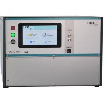
PG 12-400, 12kV, Impulse Wave Generator

IPG 1218 / 1012 / 605, Insulation Test, 12kV, 10kV, 6.25kV

IPG 255, Insulation Tester, 8kV
PG 24 - 2500 Surge Test Generator
AC-Tester 6, 10 kV Alternating voltage, Isolation testing set
PG 20 - 4000, High Voltage Pulse Generator, 10/700µs, 5/320µs, 20kV
PG 14 - 1960, High Voltage Pulse Generator, 10/700µs, 0.5/700µs, 14kV
PG 12 - 1440, High Voltage Pulse Generator, 10/700µs, 1.2/50µs, 12kV
PG 5-200 / PG 10-1000, High Voltage Pulse Generator, 10/700µs, 5/350µs, 1.2/50µs

PG 20-100 Solar modules test, 20kV
PG 10-200 / PG 12-360, Solar modules test, 10kV & 12kV
PG 10-150, Flammability test, 10kV

IPG 809, Capacitor Tester, 8kV
IPG 506: FRONT-CHOPPED-WAVE GENERATOR
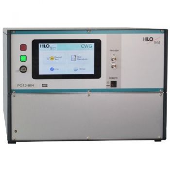
PG 12-804 12kV Surge CWG
IPG 506 SYM: FRONT-CHOPPED-WAVE, 3-Pole DUT

