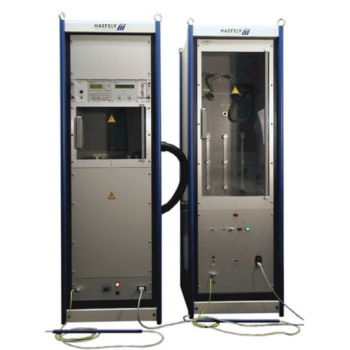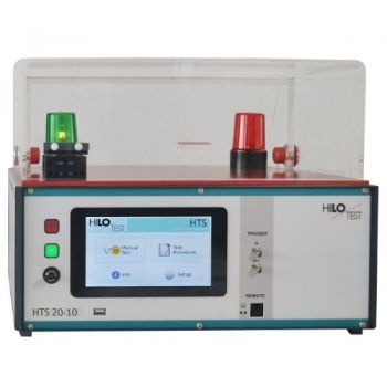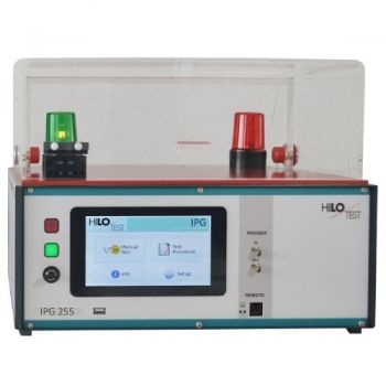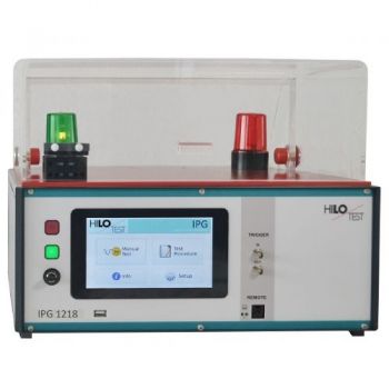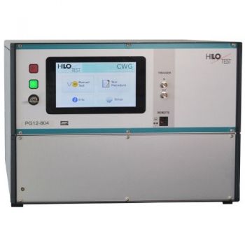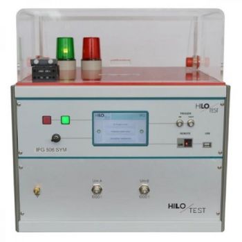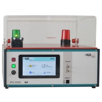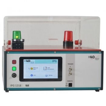
PG 24 - 2500 Surge Test Generator
The Surge Test Generator PG 24-2500 is a combined impulse current-/impulse-voltage generator which, for high-impedance loads, RL > 100?, delivers a standard impulse voltage with waveform 1.2/50µs and, for short-circuited output, a standard impulse current with waveform 8/20µs, as defined by IEC 60. The peak value of the pulse output voltage can be adjusted from 0.5 kV to 24 kV. The peak short circuit current amplitude is 12 kA.
PARTNER:
MARKETS:
TEST STANDARDS:
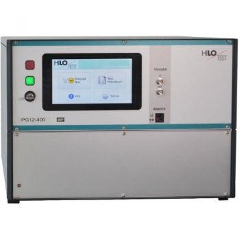
Surge Test Generator PG 24 - 2500
Surge coltage: 1.2/50 µs, 0.5-24 kV
Surge current: 8/20 µs, 0.2 - 12 kA
acc. to: IEC 61000-4-5, IEEE 587
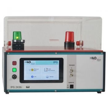
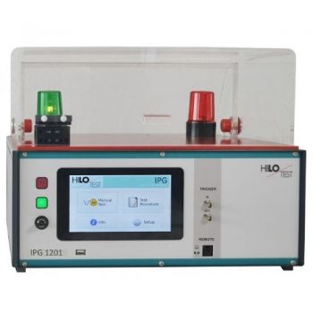
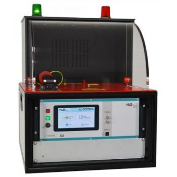
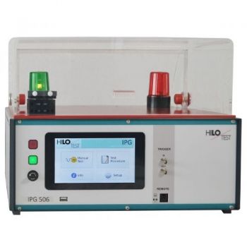
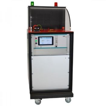
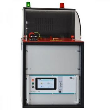
(Above Picture with test cover PA504 = option)
The Surge Test Generator PG 24-2500 is a combined impulse current-/impulse-voltage generator which, for high-impedance loads, RL > 100W, delivers a standard impulse voltage with waveform 1.2/50µs and, for short-circuited output, a standard impulse current with waveform 8/20µs, as defined by IEC 60. The peak value of the pulse output voltage can be adjusted from 0.5 kV to 24 kV. The peak short circuit current amplitude is 12 kA.
The generator is designed for dielectric testing of components and systems or direct coupling to cable shields and shielding enclosures. PG 24-2500 consists of a microprocessor controlled control- and monitoring unit and a high-voltage unit, which contains the energy storage capacitor, the high-voltage switch and the pulse forming network.
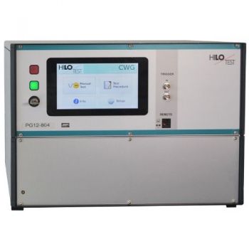
PG 24-2k5 features a microprocessor controlled user interface and a 5” touch screen unit for ease of use. The microprocessor allows the user to execute either standard test routines or a “user-defined ” test sequence. The test parameters, which are shown on the built-in display, are easily adjusted by means of the touch screen.
A standard USB port provides the ability to print a summary of the test parameters to a USB stick.
Moreover, all generator functions may be computer controlled.
The software program PG-REMOTE allows full remote control of the test generator via fiber optic Ethernet interface as well as documentation and evaluation of test results, accordingly to the IEC 17025. To record definite impulses, it is equipped with an Impulse Recording Function (IRF).
|
Technical specification: |
PG 24-2500 |
|
|
|
|
Mainframe, control unit: |
|
|
Microprocessor controlled touch panel |
5”, 800X480, 24 bit |
|
Optical Ethernet Interface for remote control of the generator |
optional |
|
Interface for saving reports |
USB |
|
|
|
|
External Trigger input |
10 V and 1 kW |
|
Connector for external safety interlock loop |
24 V = |
|
and external red and green warning lamps acc. to VDE 0104 |
230 V, 60W |
|
Mains power supply |
230 V , 50/60 Hz |
|
|
|
|
Dimensions: 19"-cabinet, W * H * D |
556*620*800 mm3 |
|
Weight |
115 kg |
|
|
|
|
|
|
|
HV-impulse generator: |
|
|
Peak value of the open-circuit output voltage |
0.5 - 24 kV ± 10 % |
|
Waveform acc. to IEC 60, VDE 0433 |
1.2 / 50 µs ± 30 %/±20 % |
|
Peak value of the short-circuit output current |
0.2 - 12 kA ± 10 % |
|
Waveform acc. to IEC 60, VDE 0433 |
8 / 20 µs ± 20 % |
|
Polarity of surge output voltage / output current |
pos/neg/alt selectable |
|
max. stored energy |
2500 Joule |
|
Charging time at max. charging voltage |
< 40s |
|
HV-output: High current terminals on the rear panel |
HV-OUT |
|
|
|
|
Mains synchronous triggering: Phase shifting, digitally selectable |
0 - 360 °, step 1° |
|
Display of peak values of impulse voltage and impulse current |
build in |
|
Monitor output for impulse voltage |
2000 : 1 ± 5 % |
|
Monitor output for impulse current |
12V º 12 kA ± 5 % |
|
Ground rod, for manual security earthing of the HV output |
build in |
|
|
|
|
Option: |
|
|
Software PG-Remote for remote control 5 m fiber-optic cable and PC-interface |
|
|
|
|
|
Option : |
|
|
Safety test cover PA 504 mounted on the top Limit switch connected to the safety interlock loop Test space: W*H*D |
430*280*500 mm |
|
|
|


