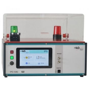
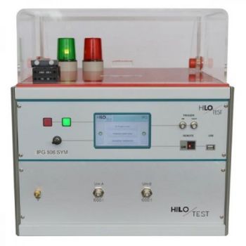
IPG 506: FRONT-CHOPPED-WAVE GENERATOR
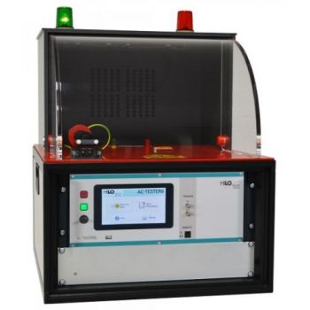
The front-chopped-wave generator IPG 506 is used for measuring dc spark-over voltage and impulse spark-over voltage of over-voltage protectors according to CCITT / ITU-T, K12. Dc spark-over voltage: A linearly rising voltage, rate of rise 100 V/s up to 640 V, is connected to the device under test. The spark-over voltage measured is shown in the display. Impulse spark-over voltage: A linearly rising impulse voltage, rate of rise 100 V/µs up to 5000 V/µs, open loop amplitude 5000 V, is connected to the device under test. The spark-over voltage is measured by use of a peak detector. The result is shown in the display. A built-in impulse voltage divider allows measurement of the spark-over voltage by use of an externally connected scope. Picture: incl. Option PA 503
PARTNER:
MARKETS:
CATEGORIES:
TEST STANDARDS:

Data Sheet
SPECIFICATIONS
IPG 506
FRONT-CHOPPED-WAVE GENERATOR
Measurement of dc spark-over voltage and impulse spark-over voltage
Rise of output voltage, selectable: 600 V= : 100 V/s
5 kV impulse: 100V/µs - 5000 V/µs Insulation resistance 0.5 - 3 GW
|
According to |
|
CCITT / ITU-T, K12 |
The front-chopped-wave generator IPG 506 is used for measuring dc spark-over voltage and impulse spark-over voltage of over-voltage protectors according to CCITT / ITU-T, K12.
Dc spark-over voltage:
A linearly rising voltage, rate of rise 100 V/s up to 640 V, is connected to the device under test. The spark-over voltage measured is shown in the display.
Impulse spark-over voltage:
A linearly rising impulse voltage, rate of rise 100 V/µs up to 5000 V/µs, open loop amplitude 5000 V, is connected to the device under test. The spark-over voltage is measured by use of a peak detector. The result is shown in the display. A built-in impulse voltage divider allows measurement of the spark-over voltage by use of an externally connected scope.
Moreover, the insulation resistance of the test device can be measured in the range of 0.5 – 3 GW. Test voltage selectable: 50 / 100 V.
The high-voltage output terminals are located on the top of the generator. They are protected by a dielectric cover with safety interlock.
A switch-unit can be integrated, which allows successive testing of up to 8 devices.
The generator excels by its compact design, simple handling and precise reproducibility of test impulses. It features a microprocessor controlled user interface and a 7” touch screen unit for ease of use. The microprocessor allows the user to execute either standard test routines or a “user-defined” test sequence. A standard USB port provides the ability to print a summary of the test parameters to a USB stick.
The software program IPG-REMOTE allows full remote control of the test generator via Ethernet light guide as well as documentation and evaluation of test results, accordingly to the IEC 17025. To record definite impulses, it is equipped with an Impulse Recording Function (IRF) Moreover all generator functions may be computer controlled via the isolated optical interface.
|
Options |
IPG 506 |
|
|
|
|
Software IPG-REMOTE, for remote control |
|
|
With Impulse Recording Function (IRF) |
|
|
( XP, WIN7, WIN10 ) incl. 5m long light guide and PC Ethernet interface |
|
|
|
|
|
PROTECTIVE COVER ON THE EQUIPMENT TOP |
|
|
With safety interlock switch, connected to the safety interlock loop, red and green warning lamps installed acc. VDE 0104. |
See picture |
|
Typ PA 503, Dimensions W * H * D |
400 * 140 * 300 mm³ |
|
Typ PA 505, Dimensions W * H * D |
400 * 250 * 400 mm³ |
|
TECHNICAL SPECIFICATION |
IPG 506 |
|
|
|
|
Mainframe |
|
|
Microprocessor controlled touch panel |
7”, capacitive |
|
Optical Ethernet Interface for remote control of the generator |
Optional |
|
Interface for saving reports |
USB |
|
External Trigger input/ output |
Switch/ 10V |
|
Connector for external safety interlock loop |
24 V= |
|
External red and green warning lamps |
230V / 60 W |
|
Mains power |
90V – 264V / 50/60 Hz |
|
Dimensions of desktop case W * H * D |
450*180*500 mm3 |
|
Weight |
18kg |
|
|
|
|
Generator section |
|
|
Output terminals Switch-unit for successive testing of 8 devices |
8HV x 4 mm Ø, connector 1GND x 4 mm connector |
|
|
|
|
Dc spark-over voltage |
|
|
Test voltage, controlled by a 12 bit DAC |
640 V |
|
Rate of rise |
100 V/sec |
|
Measurement of spark-over voltage, accuracy |
12 bit |
|
|
|
|
Impulse spark-over voltage |
|
|
Test voltage, amplitude of the open loop impulse voltage |
5 kV ± 10% |
|
Rate of rise, selectable |
100/200/500 V/µs |
|
|
1000/2000/5000 V/µs |
|
Repetition time, selectable |
5 - 1000 sec |
|
Number of pulses, selectable |
1 - 1000 |
|
Polarity of output voltage, selectable |
pos/neg |
|
Max. stored energy |
6 Joule |
|
Measurement of spark-over voltage |
500 - 1500 V +5%/-15% |
|
Monitor output for impulse output voltage |
ratio 1000:1 ± 3% |
|
|
|
|
Measurement of insulation resistance |
|
|
Measuring range of insulation resistance |
0.5 kW - 3 GW |
|
Test voltage selectable |
50 V / 100 V |
OTHER PRODUCTS IN THE SAME CATEGORY:

HTS 20-10, 20 kV, DC dielectric strength

IPG 1201, Insulation Tester, 12kV

IPG 2025 / IPG 2436, Impulse Wave Generator 20kV or 24kV
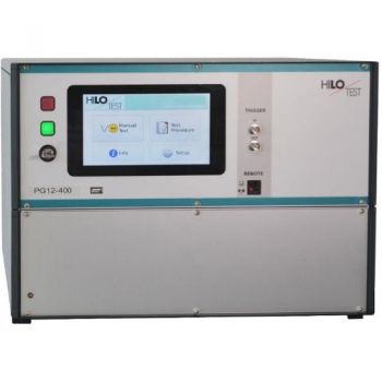
PG 12-400, 12kV, Impulse Wave Generator

IPG 1218 / 1012 / 605, Insulation Test, 12kV, 10kV, 6.25kV

IPG 255, Insulation Tester, 8kV
PG 24 - 2500 Surge Test Generator
AC-Tester 6, 10 kV Alternating voltage, Isolation testing set
PG 20 - 4000, High Voltage Pulse Generator, 10/700µs, 5/320µs, 20kV
PG 14 - 1960, High Voltage Pulse Generator, 10/700µs, 0.5/700µs, 14kV
PG 12 - 1440, High Voltage Pulse Generator, 10/700µs, 1.2/50µs, 12kV
PG 5-200 / PG 10-1000, High Voltage Pulse Generator, 10/700µs, 5/350µs, 1.2/50µs

PG 20-100 Solar modules test, 20kV
PG 10-200 / PG 12-360, Solar modules test, 10kV & 12kV
PG 10-150, Flammability test, 10kV

IPG 809, Capacitor Tester, 8kV
IPG 506: FRONT-CHOPPED-WAVE GENERATOR
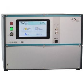
PG 12-804 12kV Surge CWG
IPG 506 SYM: FRONT-CHOPPED-WAVE, 3-Pole DUT

