Understanding GTEM EUT & Layout
Understanding GTEM EUT & Layout
Introduction
The GTEM CELL is a TEM waveguide with an upper-frequency limit extended to the GHz range. It is considered an alternative measurement facility for radiated emission and immunity measurements. It is included in the standard IEC 61000-4-20 “Emission and Immunity Testing in Transverse Electromagnetic (TEM) Waveguides.”
Compared to other measuring methods like the EMC test in anechoic chambers or OATS (Open Area Test Sites), GTEM-cells offer some significant advantages for testing small and medium-sized EUT´s (Equipment Under Test) up to a frequency range of 20 GHz. Quick turnarounds of the EUT and numerous testing variations are easy and fast to handle. Switching from emission to immunity testing requires only simple adjustments from the receiver input to the amplifier output. You are irrespective of long waiting times associated with off-site test labs or weather and ambient delays that can occur at OATS facilities. Whether you are at the design qualification, pre-compliance, compliance, or production sampling stage, the GTEM is the right choice!
Key Features
- Ruggedized, fully hot galvanized, and INOX steel construction
- Unique compact design with new Apex impedance matching transition
- Optimized for EMI and EMC
- Strong fields achieved with low input power
- Broadband line and termination up to 20GHz
- Excellent quality at a low cost
Installation manual and general safety instructions
The GTEM (Giga Hertz Transverse Electromagnetic) cell is a precision electromagnetic compatibility (EMC) test instrument primarily intended for use as radiated immunity and radiated emission test facility without environmental electromagnetic interference. The cell is electrically similar to a coaxial cable with one side open (the apex), and the other side closed on the impedance of the generator or receiver connected. In this case, with a multimeter appears a 50 Ohm resistance.
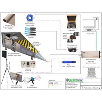
Measurement setup
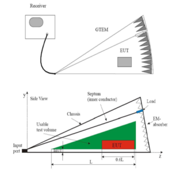
The setup for emission measurements in a GTEM cell is shown in Fig. 1. The EUT is placed inside the GTEM and its radiation is measured with a receiver. The receiver can be software controlled, and some software that includes the GTEM to OATS correlation is commercially available.

Fig.1 – Diagram of usable test volume in a GTEM cell, longitudinal section

Fig.2 - Maximum EUT size and maximum size of the usable test volume in a GTEM cell, longitudinal section

Fig.3 Maximum EUT size and maximum size of the usable test volume in a GTEM cell, cross-section
Calculating Power Required - Theory
Basically, we have to consider the volts per meter, the height of the septum, the allowance of voltage peaks caused by amplitude modulation, and the flatness with frequency. For flatness, we generally allow 3 dB. This only takes effect after the first resonance point.
The example above shows 10 V/m with:
• GTEM 450 Septum height = 0.45 m
• Flatness = 3, dB = 2
• Power Required = [ (E x h)2 /R] x Flatness x Modulation Allowance
• E [V/m] = required field strength: (i.e. 10V/m)
• h [m] = septum height
• R = GTEM input impedance (50 Ohm)
• Power Required = [(10 x 0.45)2/ 50] x 2 x 3.24 = 0.24 Watt