Measure and Remove Unwanted Harmonics, Part 2
Measure and Remove Unwanted Harmonics, Part 2
For Radiated Immunity Testing
By Jason H. Smith
Absolute EMC llc.
Measuring Harmonics
One of the acceptable ways to measure harmonics is to use a frequency selective method. Measurements are performed with an antenna, attenuator, and spectrum analyzer/receiver. The main reason for the attenuator is to protect the input of the SA/Receiver from damage. It is not acceptable to rely on the internal attenuation of such a sensitive, expensive device; an external attenuator should always be used since we know how high the levels are. The attenuator also benefits from providing a better match of the antenna to 50? of the SA/Reciever.
Setup Knowns
- Target field level with the fundamental frequency, e.g., 200 V/m
- Antenna factor of the receive antenna, e.g., 25.26 dB/m @ 200 MHz
- need table or chart as this verys greatly with frequency
- Max input power/level of receive antenna, e.g., 5 watts
- Max input level for SA/Reciever, e.g., +120 dBµV (may also be listed in dBm)
One must choose a receive antenna that will not be overloaded and burn up from high fields. It needs to be broadband. The more broadband, the better. Measuring both the fundamental and harmonic with the same antenna is desired for ease of setup and reduced error.
To use all these values, we need to convert them to comparable units. Using the above example numbers:
200V/m to dBµV/m:
- 20 log (200V/m) + 120 = 166 dBµV/m
Target level through antenna:
- Field level – AF (Antenna Factor) – Losses&Attenutation = Measured field (SA/Recever)
- Disregard losses and attenuation at this point
- 166 dBµV/m – 25.26 dB/m = 140.74 dBµV/m
- AF changes with frequency use the lowest value in the test band
Check the power of the antenna is not overloaded:
- Watts through antenna
 =2.37 watts
 - Less than 5 watts !!
Note: a better Antenna factor of just 3.26 dB (22dB/m) would reach the 5 Watt threshold of this particular antenna, making it unusable. For high fields, better antenna efficiency is not desired. To find the field limit allowed for this frequency, use this equation:

Receiver input limit check:
- Max input – input level = attenuation needed
- 120 dBµV/m – 140.74 dBµV/m = -20.74dB (negative # use attenuator)
- => use 30 dB attenuation
Suggested Receive Antennas:
Band 30 MHz – 200 (333) MHz
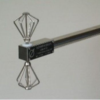
- UBAA 9114 + BAOC 9216 - Small Biconical antenna – 30 - 1000MHz, 5 watts
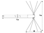
- Measuring up to 3rd harmonic 1000MHz
Band (80) 200 MHz – 1000 MHz
- SBA 9113 B - Small Biconical antenna – 80 – 3000 MHz, 20 watts
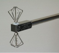
- Measuring up to 3rd harmonic 3 GHz
Band 1 GHz – 6 GHz
- SBA 9112 -Mini Biconical Antenna – 1 – 18 GHz, 10 watts

- Measuring up to 3rd harmonic 18 GHz
- Alternatively, a double ridge horn antenna (1-18 GHz) could be used as the size is not as disruptive to the setup as lower frequency antennas are.
Band 6 GHz – 18 GHz
- Below 30MHz may be tested with a monopole antenna that can be calibrated. A possible option is VPMP 9241.
- Above 18GHz can be tested with BBHA 9170 for fundamentals and harmonics that fall within the band of the antenna. Testing higher frequencies should not be needed.
Procedure
Using the above antennas, place them in the same position as the field probe is during the test. Set the polarity of the received and transmit antennas to be the same (both in vertical or both in horizontal). The harmonic check is all done in the same setup as during immunity testing, with the amplifier forward power levels set to reach the required field with the field probe. The only difference is the receive antenna is now in place of the field probe. Cable losses and the added attenuation now need to be taken into account. Measure the fundamental, 2nd, and 3rd harmonics for each frequency step for the required test. There should be -15 dBc harmonics level or better for the best low error readings.
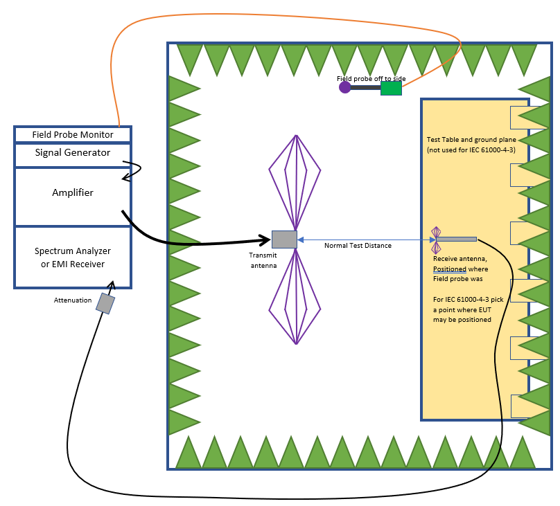
Another possible test setup is to use the receive antenna to measure just the fundamental frequency and compare it to the field probe to see if they match within an acceptable margin of error. If they are the same level, then it can be assumed harmonics did not contribute to the field probe reading. There is an added error since field probes are isotropic, and the antenna is not. I have not tested this method out to know what error to expect but assume it would vary with frequency and setups. For this reason, I do not think this is preferred.
Depending on the standard being tested, you can approach the process in 2 different ways.
- IEC 61000-4-3, where the field is calibrated to the chamber before the EUT is tested. The forward power of the amplifier is set and can allow for harmonics checks at this known level after each calibration once a year.
- MIL-STD, which is a closed-loop test, the forward power of the amplifier can change with each test. It would be best to map through the frequency range what is the maximum forward power is possible before harmonics are contributing to much to error. Once this is found forward power needs to be below this value
With all of the above setups, some assumptions can reduce testing time.
- If the power output of the amplifier is not increasing for higher fundamental frequency steps, one can assume at higher frequencies; harmonics will also not rise
- If harmonics are lowering when out of band(above the highest frequency of the amplifier or antenna), harmonics will continue to reduce for higher fundamental frequencies.
- Horn antennas can still produce gain at frequencies outside the published usable frequency band. There may be nulls and mismatches but have frequency bands of high gain.
- Log-periodic (stacked LP) antennas will not perform better outside of its usable frequency band.
Measuring up to the third harmonic of the amplifier's highest frequency may not be needed if using these assumptions.
Reducing Harmonics
Here are some tips to reduce harmonic levels
- Use a different antenna with a flat gain so that the harmonics are not "boosted up" from better gain at higher frequencies.
- Use an antenna with filtering properties such as an actively tuned Yagi from Steppir's SY3-EMC. Each frequency is tuned, resulting in harmonics having a far lower gain essentially being filtered.
- Use harmonic filters on the output of the amplifier. Filters may need to be manually attached and removed for different bands, or an automatic switch network can be used to automate the setup. System losses will add up the more switching is added.
- TWT amplifiers have inferior harmonic performance filters may be the only solution.
- Use a larger amplifier so as not to push the power levels into saturation.
- Use an isotropic frequency-selective probe for measuring field levels.
- Increase your test level to compensate for the high harmonics to guarantee the fundamental frequency is at the correct test level.
- For the last two suggestions, harmonics could still be high and affect the EUT performance but will not contribute to the fundamental frequency under testing.
