Measure and Remove Unwanted Harmonics, Part 1
Measure and Remove Unwanted Harmonics, Part 1
For Radiated Immunity Testing
By Jason H. Smith
Absolute EMC Llc.
It is a fact of life harmonics are present in RF immunity testing. A by-product of the amplification process required to produce high fields. Harmonics present themselves when there are nonlinearities in the test signal. High power amplifiers produce harmonics unless expensive filtering is implemented. Understanding the negative effects of harmonics leads us to understand what level is acceptable. There are 2 major effects from harmonics: 1) Most field probes measure all energy within the usable frequency range—high harmonics contribute to high error. It results in a lower field level at the fundamental than required for testing. 2) EUT could fail at the harmonic, but the test engineer will mark the failure down at the fundamental frequency. We will focus on the first effect on field probes concerning the accuracy of the test level. Having acceptable harmonic levels will also help the second effect.
Calculating Harmonic Influence
Field probes are not frequency-selective devices, measuring all energy with its operating range. Using diodes or thermocouples to measure the field, e-field probes from their physical design measure the e-field, but do this by measuring power then convert to a voltage level for output. The equation is simplified below for all signals within the operating band of the broadband field probe.

Usually, only one harmonic is contributing significantly to the reading simplifying the below equations. Depending on amplifier construction, the 3rd harmonic can be the highest.
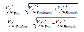
Using these equations, we can plot and see how much influence there is on the field probe reading.
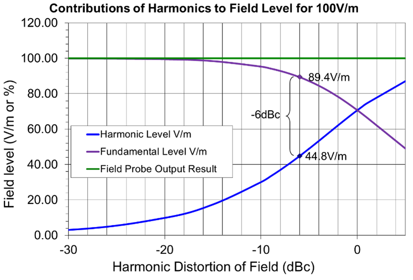
| dBc of harmonic | Field Probe Output | Fundamental Level | Harmonic Level | % error |
| dBc | V/m | V/m | V/m | |
| 0 | 100 | 70.71 | 70.71 | 29% |
| -0.2 | 100 | 71.52 | 69.89 | 28% |
| -0.5 | 100 | 72.72 | 68.65 | 27% |
| -1 | 100 | 74.65 | 66.53 | 25% |
| -1.5 | 100 | 76.52 | 64.38 | 23% |
| -2 | 100 | 78.30 | 62.20 | 22% |
| -3 | 100 | 81.62 | 57.78 | 18% |
| -4 | 100 | 84.57 | 53.36 | 15% |
| -5 | 100 | 87.16 | 49.02 | 13% |
| -6 | 100 | 89.40 | 44.81 | 11% |
| -7 | 100 | 91.31 | 40.78 | 9% |
| -8 | 100 | 92.91 | 36.99 | 7% |
| -9 | 100 | 94.24 | 33.44 | 6% |
| -10 | 100 | 95.35 | 30.15 | 5% |
| -15 | 100 | 98.46 | 17.51 | 2% |
Test Standard Requirments
Many test standards do not directly give guidance on how to measure harmonics or what is acceptable. The IEC 61000-4-3 standard allows up to a -6dBc harmonic level in the field but gives no guidance on how to measure. Harmonics of -6dBc allows for an 11% error in field reading. Other standards, like MIL-STD-461G has a short statement:
"Ensure that the E-field sensor is indicating the field from the fundamental frequency and not from the harmonics."
The statement gives little guidance on how to verify this or what is an acceptable level of error. It could be interpreted that no error is allowed, but this would be very expensive in reality. A level of -15dBc harmonic level in the field results in a 2% error in reading. An error of 2% is more acceptable than the IEC's 11% allowable error. Regardless of the test standard, it is good engineering practice that harmonics must be measured to verify a low error in setting field levels can be achieved.
Contributors to Harmonics
Signal generator – harmonics caused by the signal generator usually are not of concern when working properly.
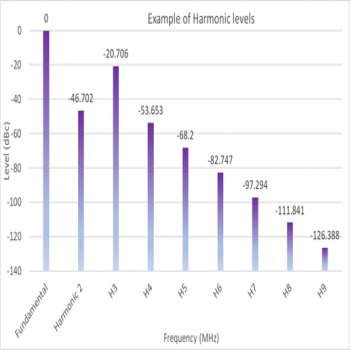
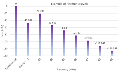
Amplifier – is the main source of the harmonics. There is a rating given by the manufacturer, e.g., -20dBc, defined that no harmonics can be less than 20dB down from the carrier signal. This is at the output of the amplifier into a 50Ω load. However, this is only below a particular power rating in the linear range (e.g., < P1dB) and may change with frequency.
- At higher power levels, harmonics should be assumed to increase.
- Depending on the amplifier design, either the second or third harmonic can be the major contributor
- Even with this low -20dBc rating, the harmonics in the field (through the transmit antenna) are contributing to error.
- The -20dBc rating is a worst-case, normally highest with the fundamental frequency near the beginning of the amplifier's band. Manufacturer production data should graph this to verify the performance.
Antenna – Transmit antennas are passive and obviously do not produce harmonics, but due to gain differences from the fundamental to the harmonics may contribute significantly to high harmonics.
- An antenna may not be an excellent match to 50Ω, which will have unknown effects on amplifier performance
- e.g., a biconical antenna's gain is about 10dB better from the fundamental frequency at 30MHz to the 3rd harmonic at 90 MHz
- e.g., a Broadband 1-6 GHz Horn antenna's gain is about 7dB better from the fundamental frequency at 1GHz to the 3rd harmonic at 3 GHz
Test Environment/Setup – cannot produce harmonics themselves but can affect the antenna performance, causing a higher VSWR in some frequency bands, which in turn has effects on the amplifier performance (causing foldback, nonlinearity).
- Antenna being used in the near field does not have the same specifications as in the far-field.
- Wavelengths are very large at lower frequencies causing coupling to ground planes, which may change VSWR of the antenna
- Reflections caused by inadequate absorber, floor ground plane, tabletop ground plane, EUT placement… can cause possible nulls or additive effects at points where the field probe is located. While having different effects between fundamental and harmonic.
Real-World Examples
Using a high power biconical antenna (30MHz – 200MHz)– just looking at manufacturers' gain data in an open area, can increase over 10dB between the fundamental to the 3rd harmonic. This takes the published 20dBc harmonics spec of the amplifier and reduces it to less than 10dBc in the field. While the biconical antenna also has very poor VSWR performance at low frequencies causing the user to push the amplifier hard, increasing power output into saturation. In saturation, harmonics will increase above the -20dBc specified level. Harmonics can increase dramatically, even producing higher levels than the fundamental frequency after going through the antenna.
Another scenario is for higher frequencies using a high gain horn antenna (1 GHz – 6 GHz). The harmonic gain can be 7dB higher than at the fundamental. 7dB – 20dBc = -13dBc in the field. This would be borderline acceptable under ideal conditions. If the amplifier needed to push higher in power into saturation to achieve the desired field level, the harmonics would rise, increasing error even further. The only way to be sure error is acceptable is to measure the harmonics directly.
In Part 2 we discuss how to make these measurements, equipment to use, and procedures.
