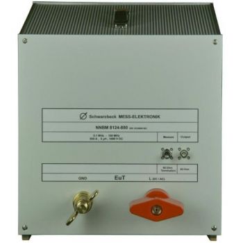
NNBM 8124, 10 kHz - 150(400) MHz, High Voltage, 70A, single path, 5µH LISN
- Acc. to CISPR 25 Ed. 4, CISPR 16-1-2, DO 160, MIL-STD, or ISO 7637-2
- impedance (5µH + 1 Ohm) || 50 Ohm
- 70 A, 1000 V (DC)
- Switchable 50Ohm Load on measurement port
- 1 microfarad capacitor to ground on AE side
- BNC-jack (Type N option)

Data Sheet
SPECIFICATIONS
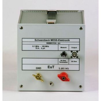
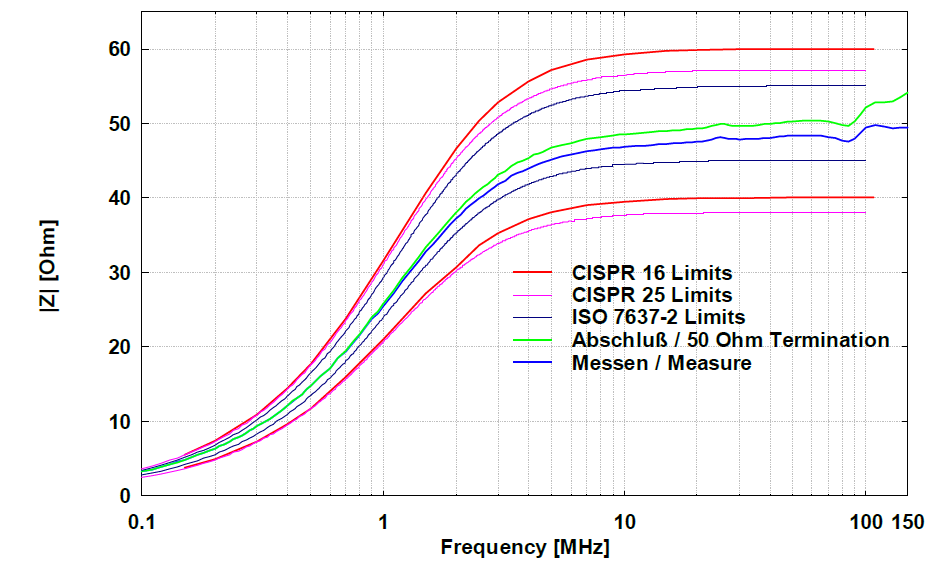
NNBM 8124, 0.1 - 150 MHz, High Voltage, 70A, single path, Automotive LISNThe main application of the unsymmetrical single path AMN (artificial mains network) NNBM 8124 is the measurement of interference voltage in vehicles, aircraft, and ships in the HF-VHF range 0.1 – 150 MHz. The NNBM 8124 can also be used for bulk current injection (BCI) testing or for transient measurements according to ISO 7637-2. The impedance characteristic is realized according to CISPR 16/25 and MIL-STD-461F (5 μH + 1 Ω) || 50 Ω. With the optional external capacitor CAP 10 it can be used for DO-160 and DEF-STAN-59 as well. The continuous current rating is 70 A, for a short time more than 100 A is possible. The EuT is connected to the wing terminals at the front panel. The mains terminals are on the backside. According to standard: CISPR 16-1-2, Annex D2, D3; CISPR 25; MIL-STD-461F; ISO 7637-2 Transients;ISO 11452-4 BCI; DO-160 (Airborne equipm.); DEF-STAN-59
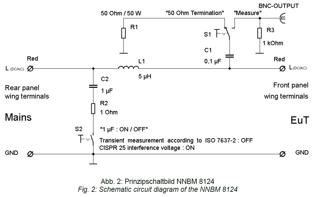
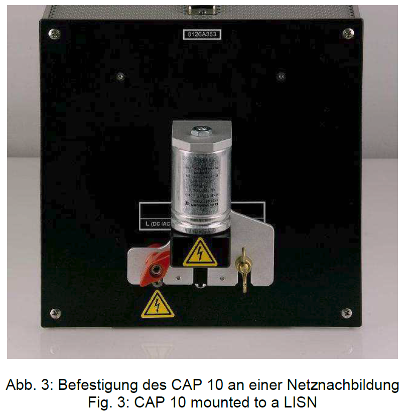
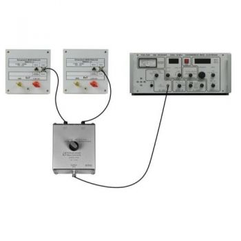
Interference voltage measurements acc. to CISPR 25 or MIL-STD-461F Mains has to be connected to the backside. The 1 μF capacitor must be switched on to filter external disturbance and to provide the best isolation values. The DuT has to be connected to the front panel. The disturbance voltage is coupled to the BNC connector where it can be measured with an EMI receiver. The switch at the front panel must be switched to “Measure”. In most cases, one AMN for each line (e.g. + and -) must be used. In this case one NNBM 8124 must be connected to the “+” line with its red terminals and another one to the “-“ line, also to the red wing terminal. The LISN of the line that is being measured has to be switched to “Measure”, the other one has to be terminated by switching the front panel switch to “50 Ohm termination”. The RFreference ground must be connected to the GND-terminals. Immunity tests with bulk current injection (BCI-tests): The NNBM 8124 can be used for bulk current injection tests utilizing a current injection clamp. The maximum continuous power rating is 50 W (at the EuT-terminals). Under continuous load at 50 W, the LISN housing heats up to approx. 60 °C at the front panel. The operator must be aware of high temperatures. The top and bottom perforated metal plates of the NNBM 8124 must not be covered under any circumstances! A sufficient air-circulation must be provided at any time to avoid overheating of the LISN. Transient measurements acc. ISO 7637-2 The NNBM 8124-200 can be used to measure transients according to ISO 7637-2. The 1μF capacitor on the mains side could short transients and must be switched off for this purpose. Calibration acc. to DO-160 or DEF STAN 59: For a calibration, according to DO-160 or DEF-STAN-59 it is mandatory to connect a 10 μF capacitance to the mains terminals. We offer a 10 μF capacitor called CAP 10 for this purpose. It fits perfectly to the wing terminals of the LISN. The built-in 1 μF capacitor must be switched off for DEF59 or DO160 measurements. Continuous high current operation: The NNBM 8124-200 is not equipped with cooling fans. If the unit is put on its own aluminum feet there is only a small slot as an air intake. Under these circumstances, the LISN can be used with a current of 800 A continuously. The maximum allowable current can be increased remarkably by propping the LISN up in a way that the air intake slot becomes larger. The perforated sheets on the bottom and top must not be covered by the props. The surface temperature at the built-in air core inductor should not exceed 150 °C. Impedance
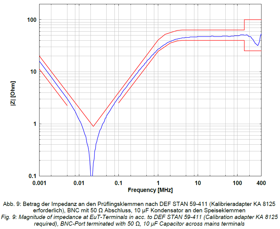
DEF-STAN Impedance down to 1kHz
|


OTHER PRODUCTS IN THE SAME CATEGORY:


AN-ABCD-60, 60 Amp Artificial Network, EV HV Testing
CABCISPR2532A, CISPR 25, 5uH, 32 A LISN
CABCISPR2515A, CISPR 25, 5uH, 15 A LISN
Cx 10000-xxx-xxx, 1000V, 100 - 600 amp 10mF HV Capacitor Cabinet
NNBM 8124, 10 kHz - 150(400) MHz, High Voltage, 70A, single path, 5µH LISN
NNBM 8124-800, 0.1 - 150 MHz, High Voltage, 800A, single path, Automotive LISN
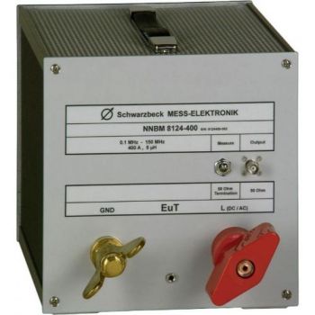
NNBM 8124-400, 0.1 - 150 MHz, High Voltage, 400A, single path, Automotive LISN
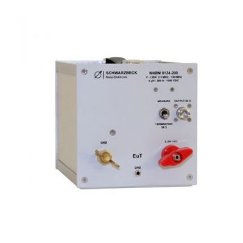
NNBM 8124-200, 0.1 - 150 MHz, High Voltage, 200A, single path, Automotive LISN
NNHV 8123-800, 0.1 - 150 MHz, High Voltage, 800A, single path, Automotive LISN
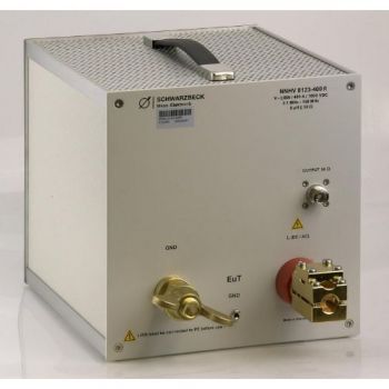
NNHV 8123-400R, 0.1 - 150 MHz, High Voltage, 400A, single path, Automotive LISN
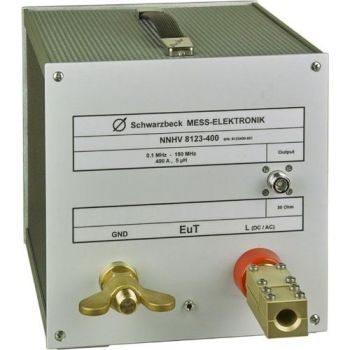
NNHV 8123-400, 0.1 - 150 MHz, High Voltage, 400A, single path, Automotive LISN
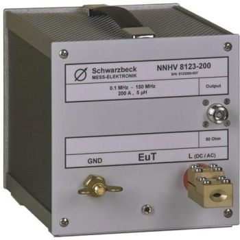
NNHV 8123-200, 0.1 - 150 MHz, High Voltage, 200A, single path, Automotive LISN
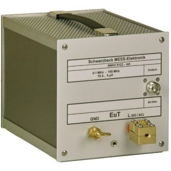
NNHV 8123, 0.1 - 150 MHz, High Voltage, 70A, single path, Automotive LISN
CMDM 8700 B Common mode / Differential mode switch
BAN 8508, BAN 8530, DC-Block 500 for testing to ISO 11452-7 or DC-10614
HVSE 8600, Shielded Enclosure for Automotive LISN
HVSE 8601, 800A Shielded Enclosure for Automotive LISN
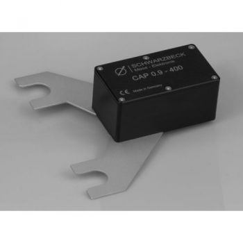
CAP 0.9-400, 0.9 µF capacitor for NNHV 8123-400/-800
VTSD 9561 F, 10dB, Diode Pulse Limiter

