BAN 8508, BAN 8530, DC-Block 500 for testing to ISO 11452-7 or DC-10614
- BAN broadband artificial network
- acc. ISO 11452-7 or DC-10614
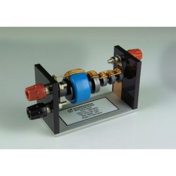
- BAN 8508, 2 A - 8 A
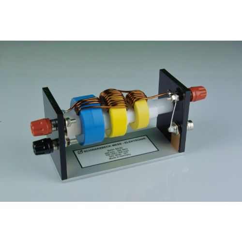
- BAN 8530, 8 A - 30 A
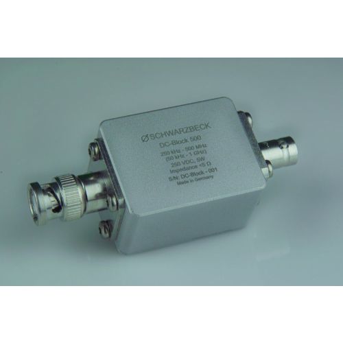
- DC-Block 500, DC-blocking capacitor

BAN 8508 Data Sheet
BAN 8530 Data Sheet
DC-Block 500 Data Sheet
SPECIFICATIONS
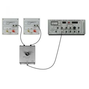
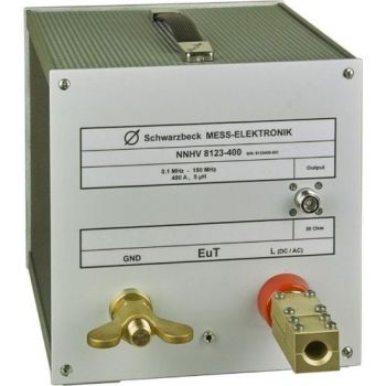
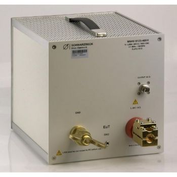
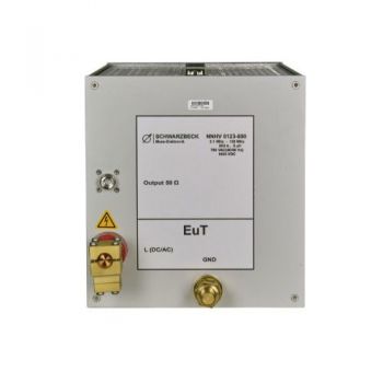
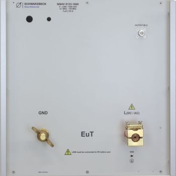
BAN 8508, BAN 8530, DC-Block 500 for testing to ISO 11452-7 or DC-10614Broadband artificial networks (BAN) are used in the automotive industry to inject radio frequency power directly into signal or power lines. This method is called “direct power injection.” The BAN provides good isolation between the AE-port and the EuT-port. The inserted radiofrequency thus is mainly directed to the EuT-port. As seen from the EuT-port the BAN provides a standard minimum impedance. The RF signal coming from the amplifier is loaded by this impedance. Larger current BAN requires larger ferrites. They have lower impedance and the decoupling is worse. For this reason, the BAN 8508 should only be used I the range 2 A to 8 A. For higher or lower currents use the suitable BAN! The BAN 8530 is specified for currents between 8 A and 30 A. Larger current BAN requires larger ferrites. They have lower impedance and the decoupling is worse. For this reason, it is not recommendable to use a BAN 8530 for less than 8 A. The basic circuit is an L/C low-pass filter. There is a broadband monolithic ceramic capacitor at the AE side. The inductance consists of five toroid core coils connected in series. The choice of the BAN depends on the maximum current and the rate of transmission of the signal. The BAN 8508 is specified for currents between 2 A and 8 A. The test setup and the measurement methods are described in the standard ISO 11452-7 or in manufacturer standards like DaimlerChrysler DC-10614 (2005-03). The BAN has to be connected in series with the device under test (DuT). Therefore the 4 mm jacks can be used. For higher currents hook type cable lugs should be used because of the lower contact resistance and less heat dissipation. The red AE-connector in ISO 11452-7 called “terminal 2” is connected with the power source of our auxiliary equipment. The black binding post on the AE-side is connected to the reference ground. It can be used for measurement purposes of the electrical properties of the BAN or as an additional ground connection. The ground connection of the BAN is already provided by the metal sheet which builds the base of BAN 8508. The BNC connector can be used to inject an RF signal from the generator/amplifier to the DuT. The BNC connector is also called “terminal 3” in the previously mentioned standards. According to the standard, a DC block capacitor has to be used. It has to be connected to the BNC jack and provides isolation between the DC on-board voltage and the RF-injection equipment. Thus the possibility of damaging the connected measurement equipment through the direct current from the onboard voltage is avoided. A suitable DC block capacitor is available as option. It is called “DC-Block 500.” For the range 8 A to 30 A the BAN 8530 is recommended. BANs for other currents or transmission rates are available on request. The solder junction for the power line of the EuT has been defined as a reference plane to measure the impedance of BAN 8508.
|
OTHER PRODUCTS IN THE SAME CATEGORY:


AN-ABCD-300, 300 Amp Artificial Network, EV HV Testing
CABCISPR2532A, CISPR 25, 5uH, 32 A LISN
CABCISPR2515A, CISPR 25, 5uH, 15 A LISN
Cx 10000-xxx-xxx, 1000V, 100 - 600 amp 10mF HV Capacitor Cabinet
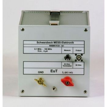
NNBM 8124, 10 kHz - 150(400) MHz, High Voltage, 70A, single path, 5µH LISN
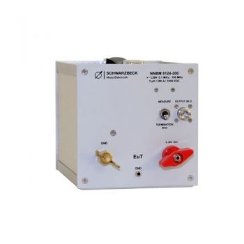
NNBM 8124-200, 0.1 - 150 MHz, High Voltage, 200A, single path, Automotive LISN
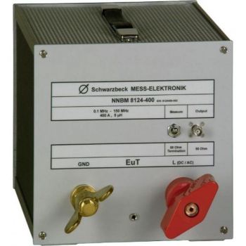
NNBM 8124-400, 0.1 - 150 MHz, High Voltage, 400A, single path, Automotive LISN
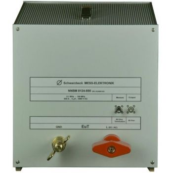
NNBM 8124-800, 0.1 - 150 MHz, High Voltage, 800A, single path, Automotive LISN
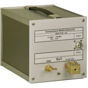
NNHV 8123, 0.1 - 150 MHz, High Voltage, 70A, single path, Automotive LISN
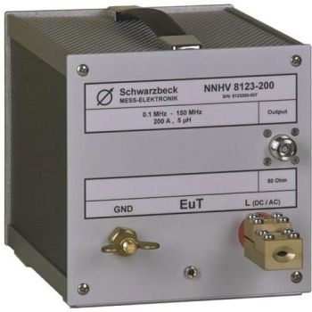
NNHV 8123-200, 0.1 - 150 MHz, High Voltage, 200A, single path, Automotive LISN
CMDM 8700 B Common mode / Differential mode switch
BAN 8508, BAN 8530, DC-Block 500 for testing to ISO 11452-7 or DC-10614
NNHV 8123-400, 0.1 - 150 MHz, High Voltage, 400A, single path, Automotive LISN
NNHV 8123-400R, 0.1 - 150 MHz, High Voltage, 400A, single path, Automotive LISN
NNHV 8123-800, 0.1 - 150 MHz, High Voltage, 800A, single path, Automotive LISN
NNHV 8123-1600, 0.1 - 150 MHz, High Voltage, 1600A, single path, Automotive LISN
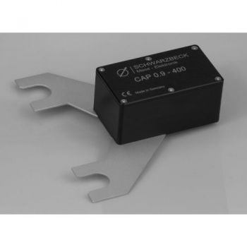
CAP 0.9-400, 0.9 µF capacitor for NNHV 8123-400/-800
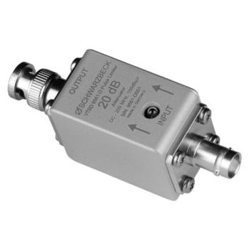
VTSD 9561 D, 20dB, Diode Pulse Limiter
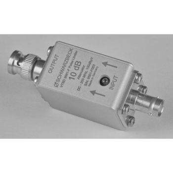
VTSD 9561 F, 10dB, Diode Pulse Limiter

