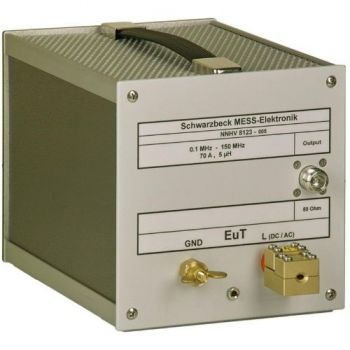
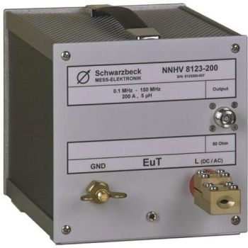
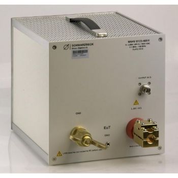
NNHV 8123-400, 0.1 - 150 MHz, High Voltage, 400A, single path, Automotive LISN
- Acc. to CISPR 25 Ed. 4 or BMW GS 95025-1
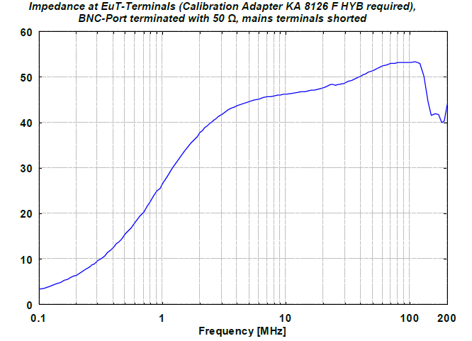
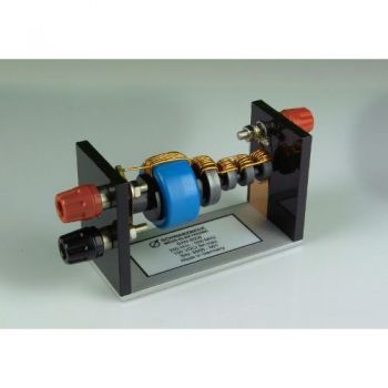
- impedance (5µH) || 50 Ohm
- 400 A, 1500 V (DC)
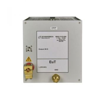
- Backside with built-in 0.1 microfarad capacitor to ground
- N-jack
SPECIFICATIONS
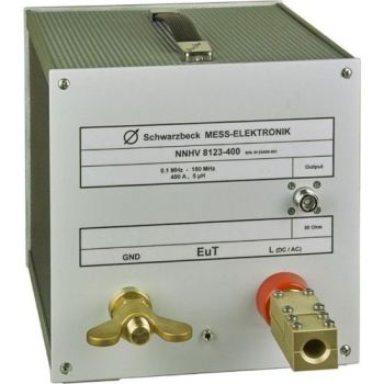
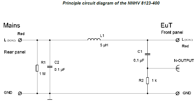
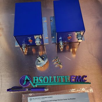
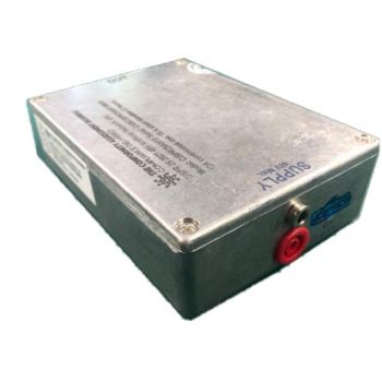
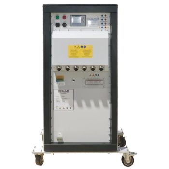
NNHV 8123-400, High Voltage, 400A Automotive LISNThe main application of the unsymmetrical single path AMN (artificial mains network) NNHV 8123-400 is the measurement of interference voltage for electromobility purposes according to CISPR 25 edition 4 or BMW GS 95025-1 in the HF-VHF range 0.1 MHz – 150 MHz utilizing shielded cables. It can also be used for BCI tests using an external 50 Ω termination. The impedance characteristics are basically realized by connecting an inductor in parallel with the input impedance of the measurement receiver: 5 μH || 50 Ω. The LISN has been designed to be installed into a shielded housing HVSE 8600 in pairs. Each NNHV 8123-400 can be used to measure one single path. To be able to measure HV+ and HV- 2 units are required. The device under test has to be connected to the terminal at the front panel. The supply voltage has to be connected at the back panel. The shield is connected to the HVSE 8600 feed through. The device under test may drain a continuous current of 250 A and for a short period of time it may even drain more than 500 A.
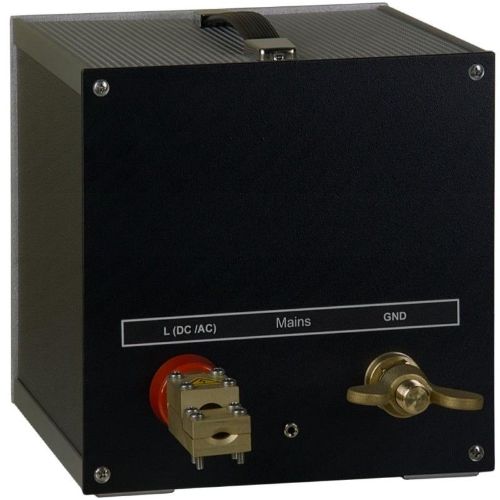
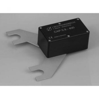
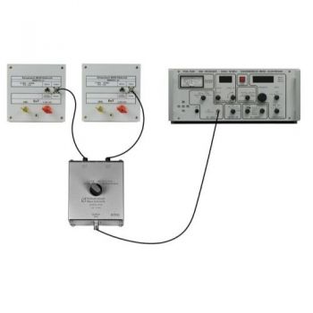
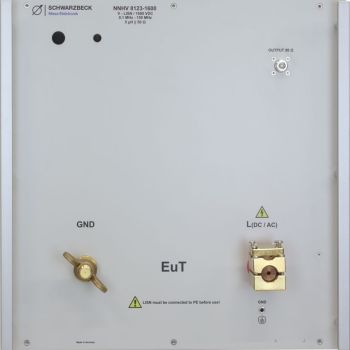
Interference voltage measurements acc. to CISPR 25 Mains are connected at the backside. The 0.1 μF capacitor located at the backside is connected to the ground. The device under test has to be connected to the front panel. For better filtering of external interference and for the best insulation values 0.9 μF capacitor (Accessory: CAP 0.9-400) can be connected to it. (0.1 + 0.9 = 1μF) The RF interference voltage emitted by the equipment under test can be measured at the N-connector using an EMI receiver. One LISN (that fits into a shielding enclosure HVSE 8600) has to be used for each path. The supply line has to be connected to the red terminal of one LISN and the return line has to be connected to the red terminal of the other LISN. The measurement port that is not being used at the moment has to be terminated with 50 Ω. The RF-ground of both LISNs has to be connected to the GND-terminals. The GND connection with the massive brass wing terminals provides the mechanical and electrical connection to the housing HVSE 8600. To connect the inner conductor of the shielded cables with the red terminal of NNHV 8123-400 it is required to duct it through the outer housing at first. When the cable end is inside the housing the screw terminals are attached and the cables can be connected to NNHV 8123-400. Two pieces of screw terminals are within the scope of delivery of the NNHV 8123-400 series. The short RF-cables to connect the measurement outputs with the housing are within the scope of delivery of the shielded enclosure HVSE 8600. Immunity tests with bulk current injection (BCI-tests): The NNHV 8123-400 can be used for bulk current injection tests using suitable current injection clamps. A sufficient air-circulation must be provided to avoid overheating of the LISN. Do not cover the LISN and the shielded enclosure! The external 50 Ω dummy load must be placed outside of the HVSE 8600 allowing good air circulation. Differences to the NNBM 8124 series: The NNHV 8123 is used for measurements on shielded DuTs in the automotive industry. Low voltage DuTs which are connected with unshielded cables are measured with the NNBM 8124 series. Both types use a 5 μH inductor and the same diameter and distance of the terminals and the same housings. Existing calibration adapters can be used for both types of AMN - LV, and HV. The NNHV 8123 series has no built-in switchable termination as the NNBM 8124 series does. The immense heat dissipation caused by BCI testing can be kept outside the shielded housing in that way. The terminals of NNHV 8123 have no threads. They consist of multiple parts to provide a possibility to duct the cables through the housing. The NNBM 8124 uses wing terminals. NNBM 8124 is usually not put into a shielded housing whilst the NNHV 8123 must be installed in pairs in the shielded housing NNHV 8601 to simulate the properties of shielded HV-networks in EV or HEV.
|


OTHER PRODUCTS IN THE SAME CATEGORY:


AN-ABCD-300, 300 Amp Artificial Network, EV HV Testing
CABCISPR2532A, CISPR 25, 5uH, 32 A LISN
CABCISPR2515A, CISPR 25, 5uH, 15 A LISN
Cx 10000-xxx-xxx, 1000V, 100 - 600 amp 10mF HV Capacitor Cabinet
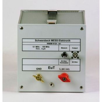
NNBM 8124, 10 kHz - 150(400) MHz, High Voltage, 70A, single path, 5µH LISN
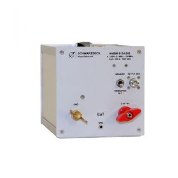
NNBM 8124-200, 0.1 - 150 MHz, High Voltage, 200A, single path, Automotive LISN
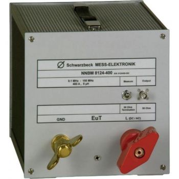
NNBM 8124-400, 0.1 - 150 MHz, High Voltage, 400A, single path, Automotive LISN
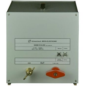
NNBM 8124-800, 0.1 - 150 MHz, High Voltage, 800A, single path, Automotive LISN
NNHV 8123, 0.1 - 150 MHz, High Voltage, 70A, single path, Automotive LISN
NNHV 8123-200, 0.1 - 150 MHz, High Voltage, 200A, single path, Automotive LISN
CMDM 8700 B Common mode / Differential mode switch
BAN 8508, BAN 8530, DC-Block 500 for testing to ISO 11452-7 or DC-10614
NNHV 8123-400, 0.1 - 150 MHz, High Voltage, 400A, single path, Automotive LISN
NNHV 8123-400R, 0.1 - 150 MHz, High Voltage, 400A, single path, Automotive LISN
NNHV 8123-800, 0.1 - 150 MHz, High Voltage, 800A, single path, Automotive LISN
NNHV 8123-1600, 0.1 - 150 MHz, High Voltage, 1600A, single path, Automotive LISN

CAP 0.9-400, 0.9 µF capacitor for NNHV 8123-400/-800
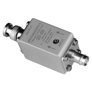
VTSD 9561 D, 20dB, Diode Pulse Limiter
VTSD 9561 F, 10dB, Diode Pulse Limiter

