Selecting a Programmable DC Power Supply for Fast, Accurate Control with Rapid Transitions
Automotive ISO testing and manufacturer requirements require a fast power supply to meet many standards.
Introduction
In modern testing environments, engineers often require programmable DC power supplies that can provide precise and rapid control. These requirements are especially critical in applications involving fast transient responses used in many standards for EMC testing or product quality life cycling. Achieving such performance necessitates careful consideration of several factors, including frequency response, rise times, fall times, and slew rates. This article delves into these aspects, with a focus on understanding how capacitance in power supplies affects fall times and the strategies employed to enhance these characteristics.
Key Parameters in Programmable DC Power Supplies
1. Frequency Response
Frequency response refers to the power supply's ability to respond to changes in load or input signals over a range of frequencies. A wide and flat frequency response ensures that the power supply can accurately follow the desired voltage or current profile without introducing significant phase delay or amplitude distortion. This characteristic is crucial for applications requiring precise control and fast transitions, as it determines how well the power supply can maintain its output stability under dynamic conditions.
2. Rise Time and Fall Time
Rise Time: The rise time is the duration taken for the output to change from a defined low value (typically 10% of the final value) to a high value (90% of the final value). It is an essential parameter for applications needing rapid voltage or current ramp-ups.
Fall Time: Conversely, the fall time is the duration for the output to transition from a high value (90%) to a low value (10%). Fast fall times are critical in applications where rapid cessation of power is required, such as in transient immunity testing or protective shutdown scenarios.
3. Slew Rate
Slew rate is defined as the maximum rate of change of the output voltage or current per unit of time, typically expressed in volts per microsecond (V/µs) or amperes per microsecond (A/µs). A higher slew rate indicates the power supply's ability to transition quickly between different output levels. It is directly related to both rise time and fall time; faster slew rates result in shorter rise and fall times.
Mathematically, the slew rate (SR) can be expressed as:
![]()
Where ![]() is the rate of change of the voltage over time.
is the rate of change of the voltage over time.
Relationship Between Slew Rate and Frequency Response
The relationship between slew rate and frequency response can be understood through the maximum frequency (![]() ) that the power supply can accurately track. The maximum frequency is determined by the highest rate of change the power supply can handle, which is directly related to its slew rate.
) that the power supply can accurately track. The maximum frequency is determined by the highest rate of change the power supply can handle, which is directly related to its slew rate.
To derive this relationship, consider a sinusoidal signal with amplitude Vpeak and angular frequency w:
![]()
The maximum rate of change (or the peak slope) of this signal occurs when cos(wt) = 1 giving:
![]()
The slew rate SR of the power supply must be at least equal to this maximum rate of change for the power supply to track the signal accurately:
![]()
Since ![]() where
where ![]() is the frequency, we can rewrite the equation as:
is the frequency, we can rewrite the equation as:
![]()
From this, we can solve for the maximum frequency ![]() :
:
![]()
This equation shows that the maximum frequency the power supply can handle is inversely proportional to the amplitude of the signal and directly proportional to the slew rate.
Practical Example
Suppose a programmable DC power supply has a bandwidth of 100 kHz and needs to handle a peak signal amplitude of 10 V. The required slew rate can be calculated as follows:
![]()
![]()
![]()
Thus, the power supply should have a slew rate of at least 6.28 V/µs to accurately reproduce signals up to 100 kHz with a peak amplitude of 10 V.
Relationship Between Frequency Response, Rise Time, Fall Time, and Slew Rate
Frequency Response and Slew Rate: The frequency response of a power supply is closely linked to its slew rate. A power supply with a high slew rate can handle rapid changes in output, which corresponds to a better frequency response at higher frequencies. This ensures minimal phase lag and amplitude variation across the operational frequency range.
Rise Time and Slew Rate: The rise time is inversely proportional to the slew rate. A higher slew rate results in a shorter rise time, allowing the power supply to quickly reach the desired output level.
Fall Time and Slew Rate: Similarly, the fall time benefits from a higher slew rate. Efficient discharge mechanisms and high-speed control loops facilitate faster voltage drops, resulting in reduced fall times.
Overall Performance: An optimized power supply should balance all these parameters to meet the specific needs of the application. For instance, in EMC testing, where precise and rapid voltage changes are necessary, the power supply must exhibit an excellent frequency response, minimal rise and fall times, and high slew rates.
Impact of Capacitance on Fall Time
Capacitance is needed to improve the output performance of some power supplies; however, it significantly impacts fall times. One of the primary reasons for using capacitors in the output stage of a DC power supply is to filter and smooth out voltage fluctuations and noise. The capacitance in the power supply, including parasitic capacitances of internal components and any added output capacitors for noise filtering, tends to slow down the fall time. This occurs because the stored energy in the capacitors needs to be discharged before the output voltage can drop, resulting in a slower response.
Strategies to Improve Fall Time
Several methods can be employed to mitigate the effects of capacitance and enhance the fall time of a programmable DC power supply:
Active Discharge Circuits:
Implementing active discharge circuits within the power supply can significantly improve fall times. These circuits actively dissipate the stored energy in the capacitors, enabling a quicker reduction in output voltage. Components such as transistors or MOSFETs are often used in these circuits to provide a low-resistance path for the discharge.
Reduced Capacitance Design:
Designing the power supply with minimal internal capacitance can inherently improve the fall time. This involves careful selection and placement of components to reduce parasitic capacitance and using smaller value capacitors where possible.
Optimized Feedback Systems:
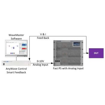
Feedback systems play a crucial role in the dynamic performance of power supplies. Optimizing these systems to minimize delay and enhance response accuracy can contribute to faster fall times.
Conclusion
Selecting a programmable DC power supply for applications requiring fast, accurate control with rapid transitions involves a thorough understanding of key parameters such as frequency response, rise times, fall times, and slew rates. Addressing the challenges posed by internal capacitance and employing strategies like active discharge circuits, reduced capacitance design, high-speed control loops, and optimized feedback systems are essential to meet stringent performance requirements. By focusing on these aspects, engineers can ensure that their power supply meets the demanding needs of modern testing environments, providing reliable and precise control under dynamic conditions.
How can Absolute EMC help in your DC power supply needs?
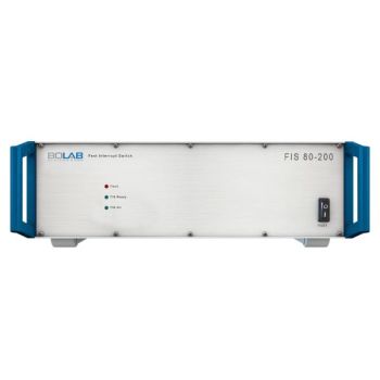
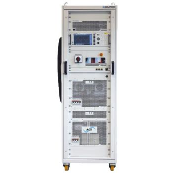
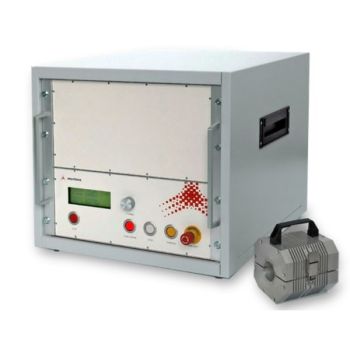
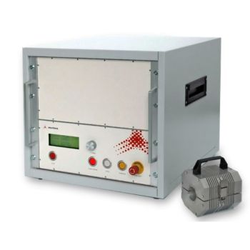
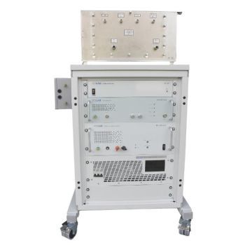
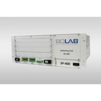
Here at Absolute EMC, we are devoted to the EMC market, offering products that live up to our trusted reputation. We offer systems from BOLAB Systems that can respond faster than most power supplies on the market. With rise AND fall times
Click here to see all of our articles.
