System Proposal for ISO 11452-2 200V/m Radiated Immunity 20MHz-6GHz with 600V/m Radar
Proposal
Date:
Reference: Request for ISO 11452-2 system
| From: | Customer: |
| Absolute EMC Llc14126 Wood Rock WayCentreville, VA 20121absolute-emc.com | |
| Contact: Jason H. SmithEmail: jason@absolute-emc.comPhone: (703) 774-7505 | Contact: Email: Phone: |
Summary of Project
ISO 11452-2 Test system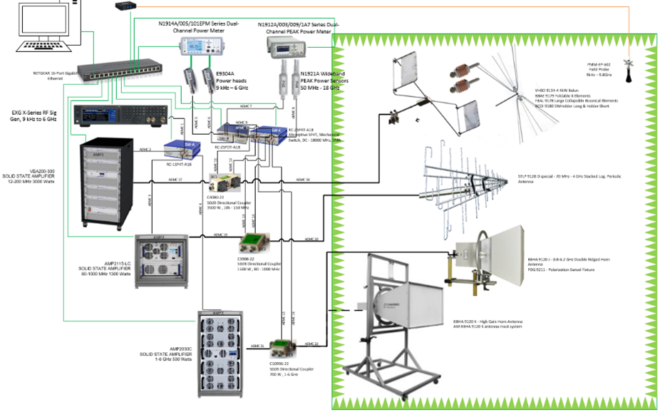
- Turnkey System run by PC (provided by Customer at their request) covers all the below requirements.
Frequency range 20 MHz – 6 GHz - Minimum Test level: 200 V/m
- Special Test Level: 600V/m 1.2-1.4 & 2.8-3.2 GHz Radar bands (FORD), pulsed modulation
- Modulation 80% AM (Conservation of Peak), other modulations possible
- Test Distance: 1 meter
- To be operated with Nexio BAT-EMC software (compatible with other 3rd party software)
- Software integration and setup responsibility of MPS
- Absolute EMC will offer support for hardware
Company Profile and Experience
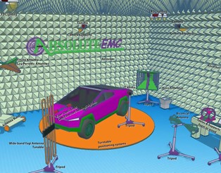 Absolute EMC offers over 20 years of experience in all phases of EMC testing. Working in Technical Applications and Sales for some of the industry's largest manufacturers extends our expertise beyond just testing, becoming experts on the equipment being used. Knowing the ins and outs of the amplifier or receiver is a requirement to meet the standards. With our wide background focused on the EMC industry, we can meet your needs no matter how large or small the requirement. We are always offering free equipment consulting to all clients.
Knowledge in the following areas:
- EMC Test system design, installation & training
- Test software setup and programming
- Emissions and Immunity testing
- Military, Avionics, Commercial, Medical, IT, Automotive
- Test plan, report template, and training documentation development
- Full or Partial Turn-Key system design and integration
- Test-site audit and improvement plans
- Hard to find EMC test equipment and accessories suggestions
- Previous membership & development on many standards committees
Description
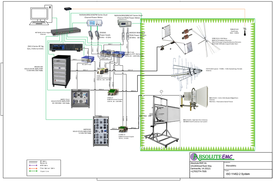
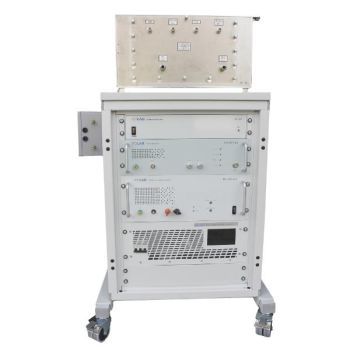
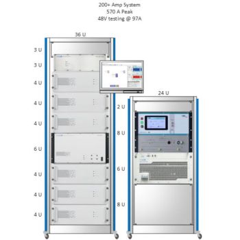
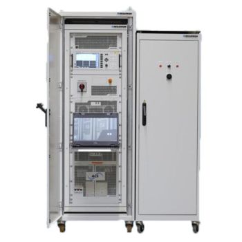
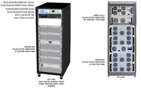
The ISO 11452-2 System is housed in 2- rolling 34U racks. RF switching is provided for easy switching of frequency bands and instruments without much user intervention. The high power output of each of the amplifiers cannot be switched and must be manually connected to each antenna for each band. This is acceptable since each antenna would require to be set up and positioned manually. All Instruments and amplifiers will be controlled through ethernet.
Test Rack Mockups
Instrumentation
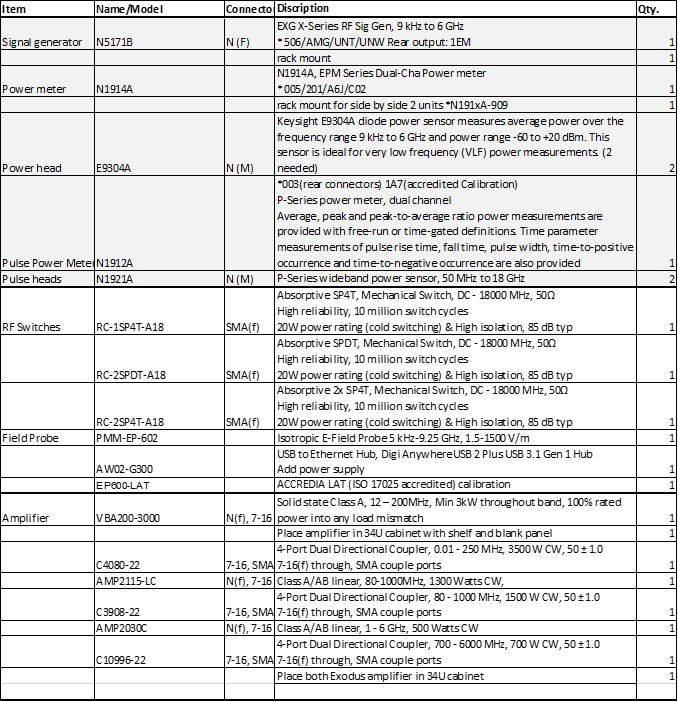
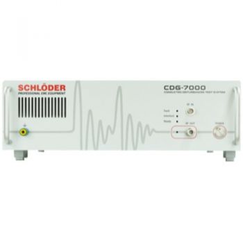
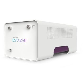
 Signal generator - N5171B – Keysight EXG X-Series RF Sig Gen, 9 kHz to 6 GHz (506/AMG/UNT/UNW Rear output: 1EM)
![]() Power meter (CW) - N1914A, Keysight EPM Series Dual-Channel Power meter (005/201/A6J/C02) Need rear connectors
Power meter (CW) - N1914A, Keysight EPM Series Dual-Channel Power meter (005/201/A6J/C02) Need rear connectors
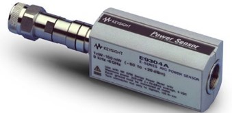 Powerheads (CW) - E9304A, Keysight E9304A diode power sensor measures average power over the frequency range 9 kHz to 6 GHz and power range -60 to +20 dBm. This sensor is ideal for very low frequency (VLF) power measurements. (2 needed)
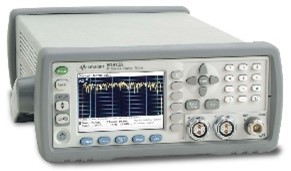 Power meter (pulsed) - N1912A P-Series power meter, dual-channel
Average, peak, and peak-to-average ratio power measurements are provided with free-run or time-gated definitions. Time parameter measurements of pulse rise time, fall time, pulse width, time-to-positive occurrence, and time-to-negative occurrence are also provided (003(rear connectors) 1A7(accredited Calibration))
![]() Powerheads (pulsed) - N1921A, P-Series wideband power sensor, 50 MHz to 18 GHz
Powerheads (pulsed) - N1921A, P-Series wideband power sensor, 50 MHz to 18 GHz
RF Switch Matrices – Absorptive SP4T, Mechanical Switch, DC - 18000 MHz, 50?, Connector Type: SMA, Mechanical SP4T switch box, High reliability, 10 million switch cycles, 20W power rating (cold switching) & High isolation, 85 dB typ
3 Units, Verified to work with NEXIO BAT-EMC 
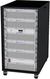 Amplifiers -
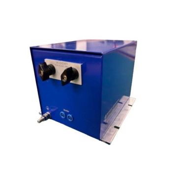
The Vectawave VBA200-3000 is a 12 – 200MHz, 3000 Watt, high power amplifier designed for applications where a rugged Class A mismatch tolerant amplifier is required. The amplifier is based on high-performance silicon push-pull MOSFET output stages and utilizes exclusive power combining techniques, minimizing loss for a more efficient solution.
Built into 34U rack, ethernet control,
Class A, 100% delivered power into any load, no foldback
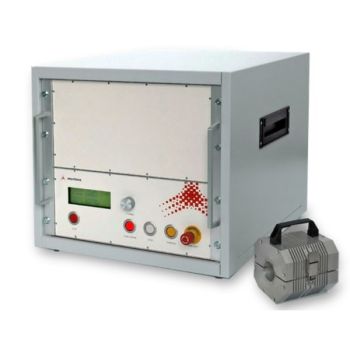
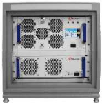 AMP2115-LC 80-1000MHz, 1300 watts, SOLID STATE HIGH POWER AMPLIFIER, Class A/AB linear
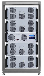 AMP2030C 700 MHz – 6 GHz, 500 Watts, SOLID STATE HIGH POWER AMPLIFIER, Class A/AB linear
Exodus Advanced technology design, Instantaneous wide bandwidth, Designed for broadband EMI/RFI, Lab, Communication applications, Suitable for all single channel modulation standards, EMC, Automotive, Built-in protection circuits, Unprecedented Quiet-Cool Technology
High reliability and ruggedness
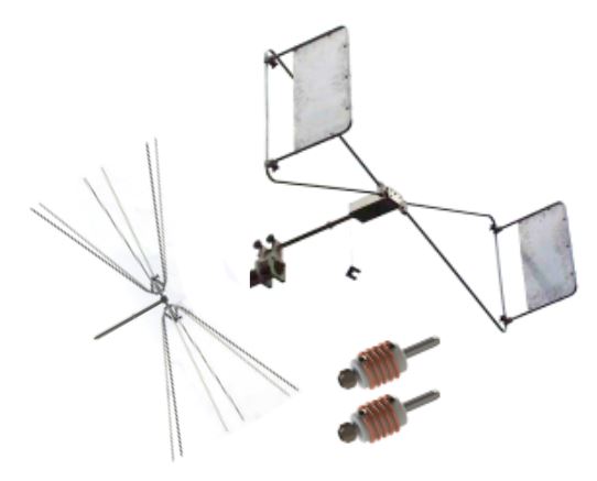 Antennas –
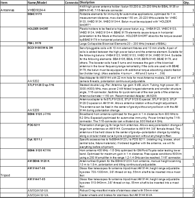
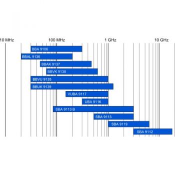
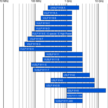
For 20 – 200 MHz testing, the following Biconical solution is provided.
VHBD 9134-4 4kW Balun
BBAE 9179 Foldable X Elements
FBAL 9178 Large Collapsible Biconical Elements
BCOI 9180 5W Loading Coils, Holder Long & Holder Short
It is very difficult to reach 200 V/m in the 20 – 100 MHz range; each chamber polarity and setup are unique. Chamber loading and reflection will happen at different frequency ranges, possibly requiring 5kW up to 10kW. Attempts to reduce the amount of power required are to approach the frequency band with multiple solutions. The High power balun can accept interchangeable elements allowing great flexibility with a very high chance of reaching the required field. This antenna rotates on-center.
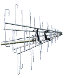 For 80 – 1000 MHz, the STLP 9128D SP antenna is proposed. It has excellent gain (~10dB) and field uniformity. This is superior to many other options on the market. This antenna overlaps with the biconical antenna and matches nicely with the proposed 80MHz to 1GHz amplifier, not requiring amplifier switching. This antenna will produce 200V/m with the provided power amplifier at a 1-meter test distance—this antenna rotates on-center.
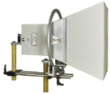 For 1 – 6 GHz testing, the BBHA 9120 J is one of the best broad frequency antennas on the market, producing the best gain for 1meter testing. This antenna matches with the amplifier frequency range, so no amplifier switching is required. This antenna will produce 200V/m at a 1-meter test distance and 600V/m in the 2.8-3.2GHz radar band. This antenna is provided with a rotation on the center adaptor.
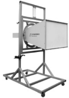 Producing 600V/m in the 1.2-1.4 GHz frequency range is difficult. A special horn antenna BBHA 912 K has been specially designed to be able to reach 600V/m with 250 Watts! Which normally requires up to 800 Watts. With system losses and some margin, the combination of this antenna and amplifier will meet the 600V/m requirement. This antenna is supplied with a specialized antenna mast system AM BBHA 9120 K
Antenna Positioners
All antennas are provided with the ability to change polarity on-center. This allows for a single person to quickly rotate the antennas and continue testing. 2 Full antenna mast systems AM 9144 are provided along with an additional vertical extension peace. The idea is to allow for easy changing of antennas without the need to do much manual setting up.
Please refer to the next page for power/loss/field calculation tables verifying performance.
Power Calculations 
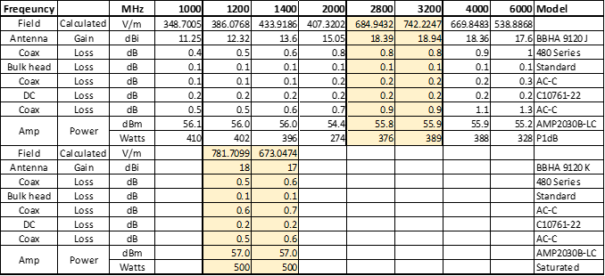
The field shown is calculated from power, losses, and antenna gain.
Coax List
| Coax | Coax Type | Connector | Length | Location | |
| AEMC 1 | AB-A | N-SMA | 1m | SG→SW-A | Rack 1 |
| AEMC 2 | AB-A | SMA-N | 1m | SW-A→Amp1 | Rack 1 |
| AEMC 3 | AB-A | SMA-N | 2m | SW-A→Amp2 | Rack 1 to Rack 2 |
| AEMC 4 | AB-A | SMA-N | 2m | SW-A→Amp3 | Rack 1 to Rack 2 |
| AEMC 5 | AB-A | N(f)-SMA | 0.5m | PH1→SW-B | Rack 1 |
| AEMC 6 | AB-A | N(f)-SMA | 0.5m | PH2→SW-B | Rack 1 |
| AEMC 7 | AB-A | N(f)-SMA | 0.5m | PH3→SW-B | Rack 1 |
| AEMC 8 | AB-A | N(f)-SMA | 0.5m | PH4→SW-B | Rack 1 |
| AEMC 9 | AB-A | SMA-SMA | 0.5m | SW-B→SW-C | Rack 1 |
| AEMC 10 | AB-A | SMA-SMA | 0.5m | SW-B→SW-C | Rack 1 |
| AEMC 11 | AB-A | SMA-SMA | 1m | SW-C→DC1-FP | Rack 1 |
| AEMC 12 | AB-A | SMA-SMA | 1m | SW-C→DC1-RP | Rack 1 |
| AEMC 13 | AB-A | SMA-SMA | 2m | SW-C→DC2-FP | Rack 1 to Rack 2 |
| AEMC 14 | AB-A | SMA-SMA | 2m | SW-C→DC2-RP | Rack 1 to Rack 2 |
| AEMC 15 | AB-A | SMA-SMA | 2m | SW-C→DC3-FP | Rack 1 to Rack 2 |
| AEMC 16 | AB-A | SMA-SMA | 2m | SW-C→DC3-RP | Rack 1 to Rack 2 |
| AEMC 17 | AB-C | 7-16 to 7-16 DIN | 0.5m | AMP1→DC1 | Rack1 |
| AEMC 18 | AB-C | 7-16 to 7-16 DIN | 2m | DC1→Chamber | Rack1 to Chamber |
| AEMC 19 | AB-C | 7-16 to 7-16 DIN | 0.5m | AMP2→DC2 | Rack2 |
| AEMC 20 | AB-C | 7-16 to 7-16 DIN | 2m | DC1→Chamber | Rack2 to Chamber |
| AEMC 21 | AB-C | 7-16 to 7-16 DIN | 0.5m | AMP3→DC3 | Rack2 |
| AEMC 22 | AB-C | 7-16 to 7-16 DIN | 2m | DC1→Chamber | Rack2 to Chamber |
RF Switch Settings
| Switch | Use | Position | ||||
| Band 1 | Band 2 | Band 3 | Band 4 (radar) | |||
| 20-200 MHz | 80-1000 MHz | 1-6 GHz | 1.2-1.4 & 2.8-3.2 GHz | |||
| RC-1SP4T-A18 | A | Signal Generator | S1-1 | S1-2 | S1-3 | S1-3 |
| RC-2SPDT-A18 | B | PM Average/Pulse | S1-1, S2-1 | S1-1, S2-1 | S1-1, S2-1 | S1-2, S2-2 |
| RC-2SP4T-A18 | C | Forward/Reverse | S1-1, S2-1 | S1-2, S2-2 | S1-3, S2-3 | S1-3, S2-3 |
AC Power Requirements
| Power | Voltage | Phase | Weight | |
| Amplifier 1 | 11kVA | 200-240V or 350-415V ac | 3Phase Delta or Star | 190kg |
| Amplifier 2 | 8 KW Max | 208 VAC | 3-phase | 60 Kg. |
| Amplifier 3 | 4500 Watt Max | 200 - 240 VAC | 1-2 phase | 120 Kg. |
Rack instruments were added up to require ~380 watts.
System Layout Diagram 