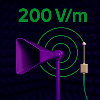
Best Antennas for 200V/m 1m testing
Generating 200 V/m at 1 m: Antenna & Fixture Guide
Electromagnetic-immunity standards such as MIL-STD-461, civil aviation DO-160/RTCA, and certain automotive OEM specs demand field strengths up to 200 V/m at a 1-metre test distance. Achieving these levels across 10 kHz – 40 GHz requires carefully selected antennas, transitions, and, at the very low end, parallel-plate or E-field generators.
1. Standards That Call for 200 V/m
|
Sector |
Frequency Range |
Typical Level |
Notes |
|
Military (MIL-STD-461 RS103) |
2 MHz – 18 GHz (40 GHz for some platforms) |
200 V/m |
10 kHz bands addressed with PPLs |
|
Aviation (RTCA/DO-160 Sec. 20, Curve L) |
200 MHz – 18 GHz |
200 V/m |
Swept and CW |
|
Automotive (OEM variants of ISO 11451/ISO 11452) |
400 MHz – 3 GHz |
100 V/m (200 V/m optional) |
Mostly radar-immunity tests |
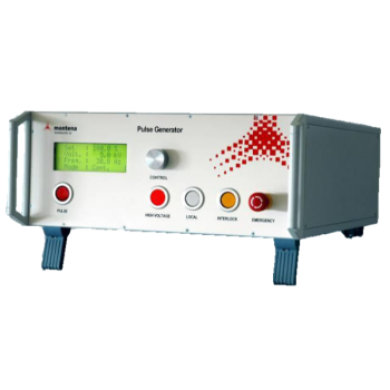
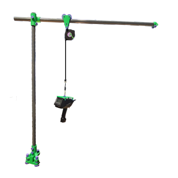
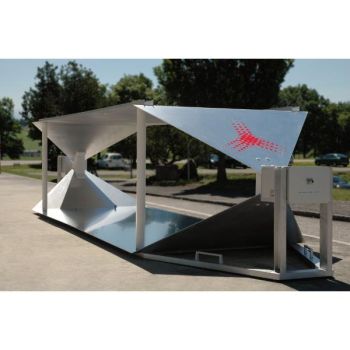
2. Low-Frequency Region: 10 kHz – 30 MHz
|
Solution |
Band |
Description |
|
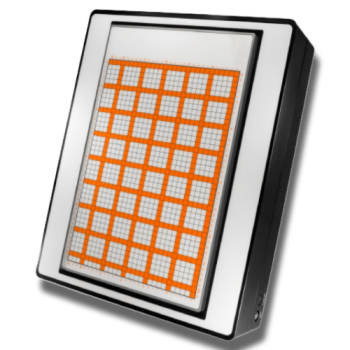
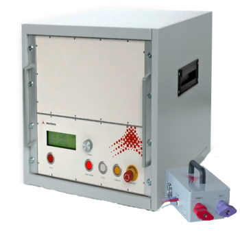
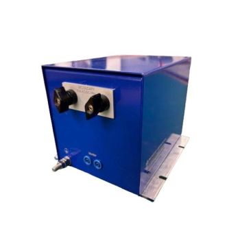
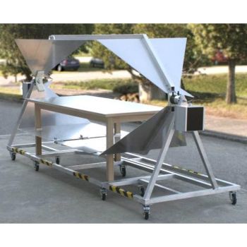
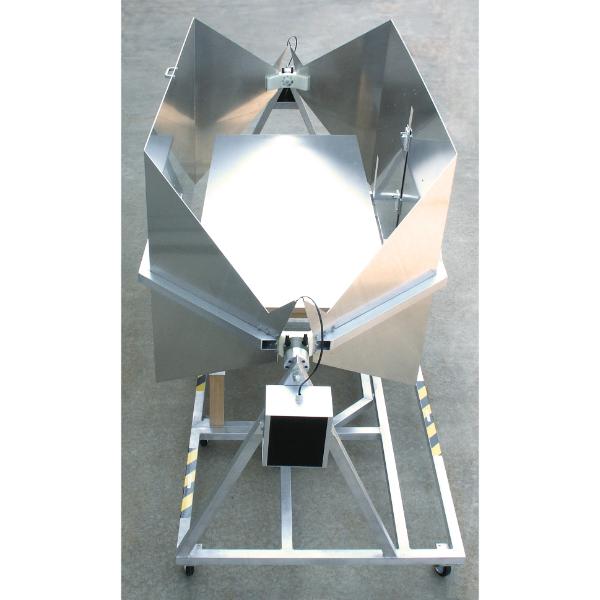
Montena PPL200 Parallel Plate |
10 kHz – 30 MHz |
500 W wheeled stand and polarization swivel. Produces uniform fields without extreme RF power. |
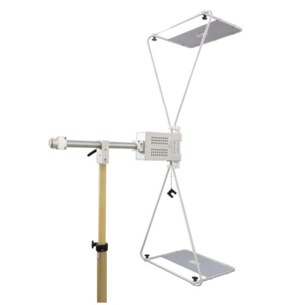
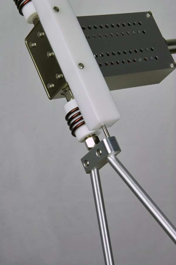
3. 30 MHz – 100 MHz: Biconical Systems
Why A biconical- Large aperture and broadband match—yet they demand kilowatts of forward power. Accessory coils and “balloon” baluns improve chamber match and reduce reflected power.
High-Power Balun
- Schwarzbeck VHBD 9134-10 – 50 Ω ↔ 200 Ω, 10 kW, 20–200 MHz, 13?30 connector.
Element Options
- TRI 0630 – Foldable 1.5 m elements, optimised for 1 m distance.
- Booster Coils (BCOI 9180xW) – 3, 4, or 5-turn plug-in coils that raise low-end gain.
- Torque Absorbers (HOLDER?-SHORT / HOLDER-LONG) – Required when heavy elements or coils add mechanical stress.
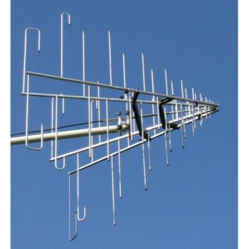
4. 80 MHz – 3 GHz: Stacked Log-Periodic
|
Antenna |
Bandwidth |
Gain @ 1 m |
Power |
|
Schwarzbeck STLP 9128 D |
80 MHz – 3 GHz (usable to 4 GHz) |
≈ 9 dBi |
2 kW (7/16 connector) |
Fast-link rear sections allow rapid removal when changing chambers or fixtures.
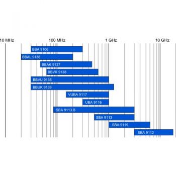
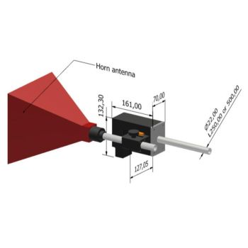
5. 800 MHz – 18 GHz: Broadband & Double-Ridged Horns
|
Band |
Preferred Antenna |
Key Specs |
|
0.8 – 6 GHz |
Schwarzbeck BBHA 9120 J |
Gain optimised at 1 m; N-connector limits to ≈ 400 W @ 4 GHz |
|
4 – 8 GHz |
Schwarzbeck HA 9251-48 |
Standard-gain horn, 19 dBi, 7/16 connector |
|
6 – 18 GHz |
Schwarzbeck HWRD-650 / -750 |
Double-ridged, 16–21 dBi, 1 kW, WRD650/750 flange; coax adapter or rigid-flange mount available |
Match each horn to the amplifier’s octave band (e.g., 1–2 GHz, 2–4 GHz, 4–8 GHz, 8–18 GHz) to maximise field with realistic amplifier power.
6. 18 GHz – 40 GHz: Waveguide Gain Horns
|
Waveguide |
Model |
Band |
Gain |
|
WR42 |
ATM 42-442-6 |
18 – 26.5 GHz |
25 dBi |
|
WR28 |
ATM 28-443-6 |
26.5 – 40 GHz |
25 dBi |
Run two waveguide horns to span 18–40 GHz, each mated directly to the amplifier flange for the lowest loss.
7. Practical Tips
- Know the Near-Field. At 1 m, you are still in the reactive zone below ~1 GHz; use measured gain (G), not far-field data.
- Calibrate Often. Verify field uniformity with isotropic probes—200 V/m tolerance is typically ±3 dB.
- Power Budget. Doubling the field (100 → 200 V/m) requires 6 dB more forward power; choose amplifiers accordingly.
- Mechanical Stability. High-power biconicals exert torque; use HOLDER-SHORT / -LONG to protect baluns.
- Fixture Repeatability. Document antenna-to-EUT distance, absorber layout, and cable routing—small changes shift the match at low frequencies.
8. Need Help?
Absolute EMC stocks and supports Montena, Schwarzbeck, ATM Microwave, and other high-power antenna lines. Our engineers will:
- Size amplifiers vs. antenna gain to hit 200 V/m with margin.
- Recommend matching accessories and mounting hardware.
- Provide on-site chamber optimisation and calibration support.
› Contact Absolute EMC to specify the right antenna stack for your 200 V/m tests.