MIL-STD-461G, Method RS103 A Creative Approach to Generating 200 V/m Fields from 30 to 200 MHz
MIL-STD-461G, Method RS103
A Creative Approach to Generating 200 V/m Fields from 30 to 200 MHz
By Jason H. Smith
Absolute EMC Llc.
Introduction
Achieving 200 V/m in accordance with MIL-STD-461G from 30 MHz to 200 MHz often poses significant challenges, particularly in the lower part of this range. This article examines the obstacles current test methods face and presents an innovative solution that enables more laboratories to perform testing successfully and in accordance with the standard.
Within this frequency band, there are few practical options for consistently generating 200 V/m. Each approach carries its own advantages and drawbacks. One critical concern is that pushing amplifiers to saturation to meet power demands can elevate harmonic outputs, which can result in erroneous field probe readings. If the test setup inadvertently uses harmonic levels to meet the overall field requirement, the reading no longer reflects the fundamental frequency’s actual field strength—contrary to the standard’s intent.
Key Test Requirements (30–200 MHz)
|
Test level: |
200 V/m |
|
Frequency step size: |
0.5% |
|
Modulation: |
1 kHz Pulse 50% duty cycle |
|
Dwell: |
≥ 3 seconds |
|
Test Distance: |
≥ 1 meter |
|
Antenna: |
Polarized |
|
Positions: |
Horizontal and Vertical |
Text from MIL-STD-461G (and similarly in version F) underscores the necessity of ensuring that the measured field emanates from the fundamental frequency, and not from harmonics. Because biconical antennas often exhibit poor low-frequency performance, the standard advises using a larger, more efficient antenna (or a transmission line radiator) below approximately 70 MHz to avoid overreliance on harmonic energy. While the standard specifically mentions this issue with biconical antennas, any test approach that relies on harmonics is ultimately non-compliant.
Harmonics and Amplifier Saturation
When amplifiers operate in or near saturation, they produce elevated harmonic outputs. If a broadband field probe is used—which integrates energy from all frequencies in its bandwidth—these elevated harmonics can artificially inflate the measured field strength. Even if a harmonic signal is 6 dB below the fundamental, the measured field can be off by around 11%. In practice:
- Many amplifiers have harmonic ratings of -20 dBc at specific power levels (e.g., P1dB).
- The third harmonic is typically the strongest (i.e., 3 × the fundamental).
- A typical biconical antenna may have a 10 dB higher gain at 90 MHz (the third harmonic of 30 MHz) than at the fundamental, effectively turning -20 dBc into -10 dBc in the field.
- A -10 dBc harmonic can account for about a 5% error. More severe amplifier saturation can yield significantly stronger harmonics, potentially causing even larger measurement errors (e.g., a 29% or greater deviation).
Therefore, amplifiers forced beyond their linear operating range exacerbate harmonic production, which can further skew field probe readings.

Figure 1. How harmonics influence a diode field probe
Compromising the Test Setup
Some laboratories attempt to reduce the required field strength distance by moving the antenna closer than the 1-meter separation specified in MIL-STD-461G. This inherently creates a test condition that is at odds with the standard’s 1-meter requirement, and any measured results may not reliably represent compliance.
Additionally, chamber effects become substantial at 30 MHz (with a corresponding 10-meter wavelength) when the antenna is just 1 meter away from the Equipment Under Test (EUT). Antennas in such close proximity often exhibit higher VSWR due to reflections and coupling, making it even more difficult to sustain a true 200 V/m at the fundamental frequency without driving the amplifier into saturation.
Antenna Limitations
Biconical antennas are commonly used for broadband testing, but they are often inefficient below 70 MHz. Although they satisfy basic requirements—broad bandwidth, relatively compact size, and good power handling—these antennas exhibit problematic VSWR in the 30–70 MHz range and minimal gain. Consequently, they usually demand large amplifier outputs to reach 200 V/m.
Other options, such as log-periodic antennas, are equally constrained by their physical size at lower frequencies and may still face challenging VSWR issues in chamber environments. E-field generators and transmission line radiators are often inadequate for 1-meter test distances at 200 V/m because they rapidly lose field strength with distance and can require impractically large amplifiers.
Challenges to Overcome
In summary, the 30–200 MHz frequency band entails:
- High VSWR caused by the antenna and additional chamber coupling.
- Low Antenna Gain in the lower portion of the band, necessitating high amplifier power.
- Amplifier Saturation leading to excessive harmonics.
- Short Test Distances that magnify near-field coupling effects.
- Inefficient Antenna Geometries when covering 30–200 MHz with a single, fixed design.
A Tunable Yagi Solution
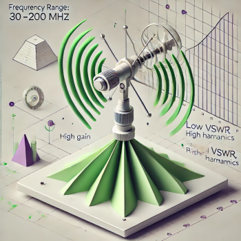
A Yagi antenna inherently provides more directional gain than a biconical or stripline radiator. While a traditional Yagi intended for 30 MHz might be prohibitively large, folding back the elements can reduce its physical size by up to 40% with only a minimal 0.3 dB loss in gain. Early versions of a tunable folded Yagi were popular in amateur (HAM) radio applications because they could automatically adjust to maintain resonance over different frequencies.
Applying this technology to MIL-STD-461 poses additional demands, such as chamber reflections and near-field conditions. Initially, manually adjusting elements for each frequency step was cumbersome and unique to each chamber setup. However, automating this process via a software-controlled system that measures VSWR and field strength and iteratively refines element lengths enables precise, repeatable tuning within a fully shielded environment.
System Components
- Tunable Yagi Antenna with fold-back elements driven by microprocessors.
- Measurement System including signal sources, spectrum analyzers, and field sensors.
- Built-In Controller that executes tuning algorithms, measuring both VSWR and field strength to optimize element lengths.
- User-control software enables the test operator to perform standard test sequencing (e.g., stepping through 0.5% frequency increments).
Once this system is tuned for a specific chamber configuration (e.g., 1-meter distance above a ground plane), the optimized settings can be stored and reused. Re-tuning is only required if significant changes are made to the test layout.
Performance and Benefits
By precisely tuning at each frequency step, the tunable Yagi ensures that:
- VSWR remains low, preventing the amplifier from saturating.
- Directional Gain is maintained, minimizing the amount of power required to reach 200 V/m.
- Harmonic Suppression is significantly improved (e.g., better than -25 dBc), ensuring the measured field is predominantly from the fundamental.
Effectively, you get a “custom antenna” at each frequency point, matched for both chamber and EUT conditions. In the MIL-STD-461G context—where 30 to 200 MHz involves roughly 382 frequency steps—this system automates an otherwise labor-intensive process, leading to reliable and repeatable test results.
Conclusion
Conventional broadband antenna options struggle to generate 200 V/m at 30 MHz without resorting to saturating high-power amplifiers, thereby risking inflated harmonic contributions and inaccurate field probe readings. By contrast, a tunable Yagi—featuring fold-back elements and automated control—offers a pragmatic alternative that reduces power demands, mitigates VSWR challenges, and delivers accurate results in challenging chamber conditions.
In short, automated tunable Yagi technology can revolutionize MIL-STD-461G testing for 30–200 MHz by reliably producing the desired 200 V/m field strength with minimized reliance on brute-force amplifier power. This approach promotes both engineering best practices and compliance with the strict requirements of modern EMC standards.
Please get in touch with Absolute EMC for your best solution, interesting high field levels of 200V/m.
