Tool-free access
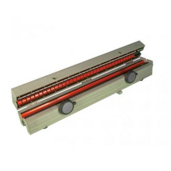
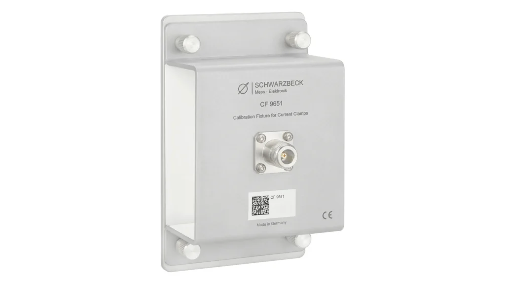
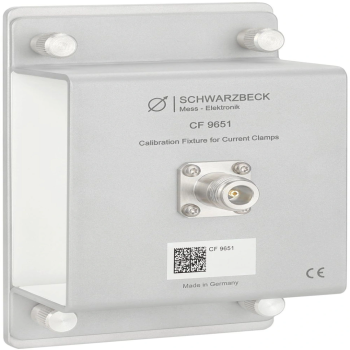
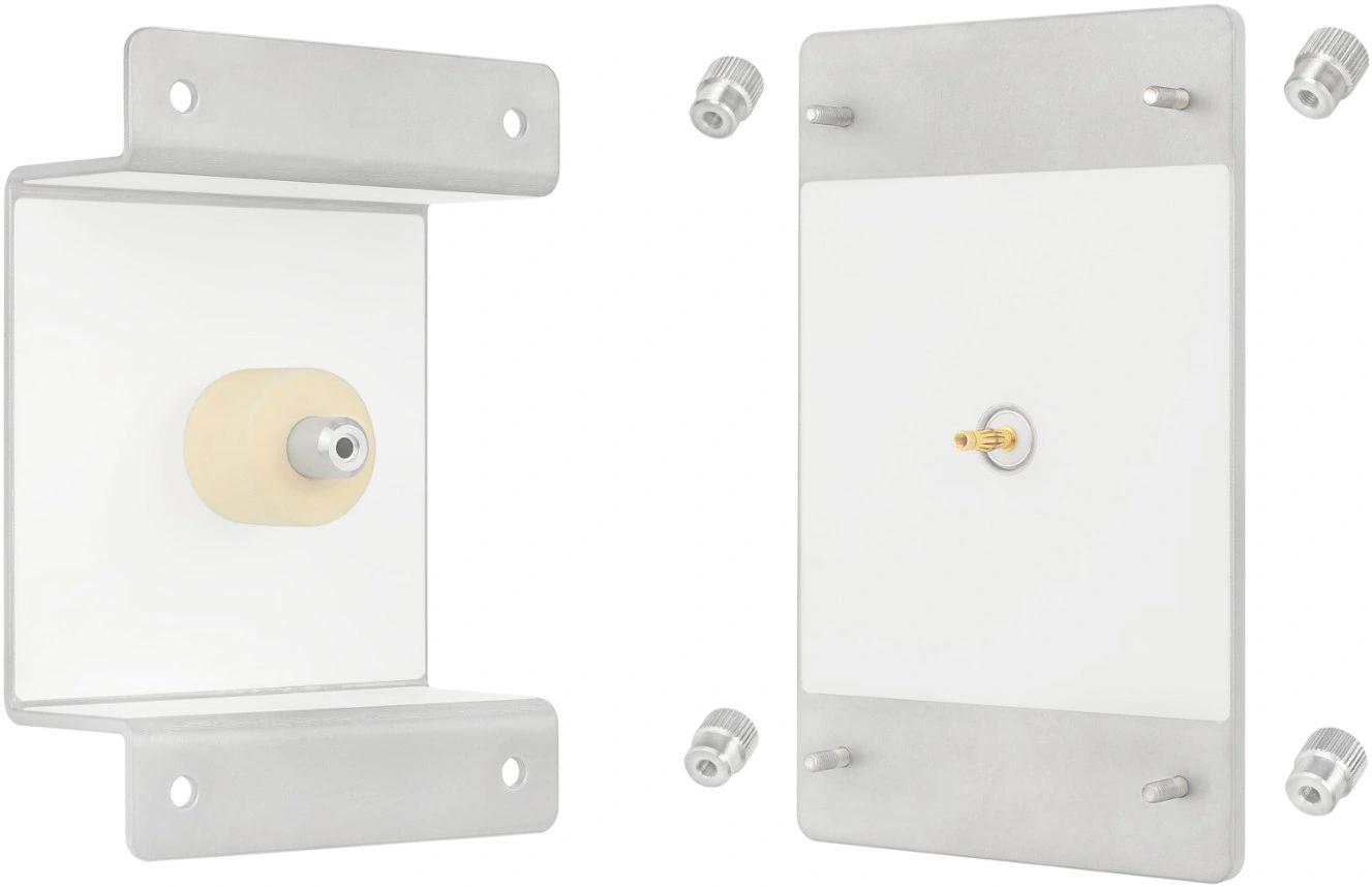
Four knurled screws allow the fixture to open and close without additional tools, making probe insertion and removal straightforward.
A defined fixture for repeatable current-clamp measurements.
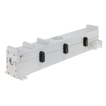
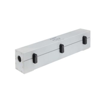
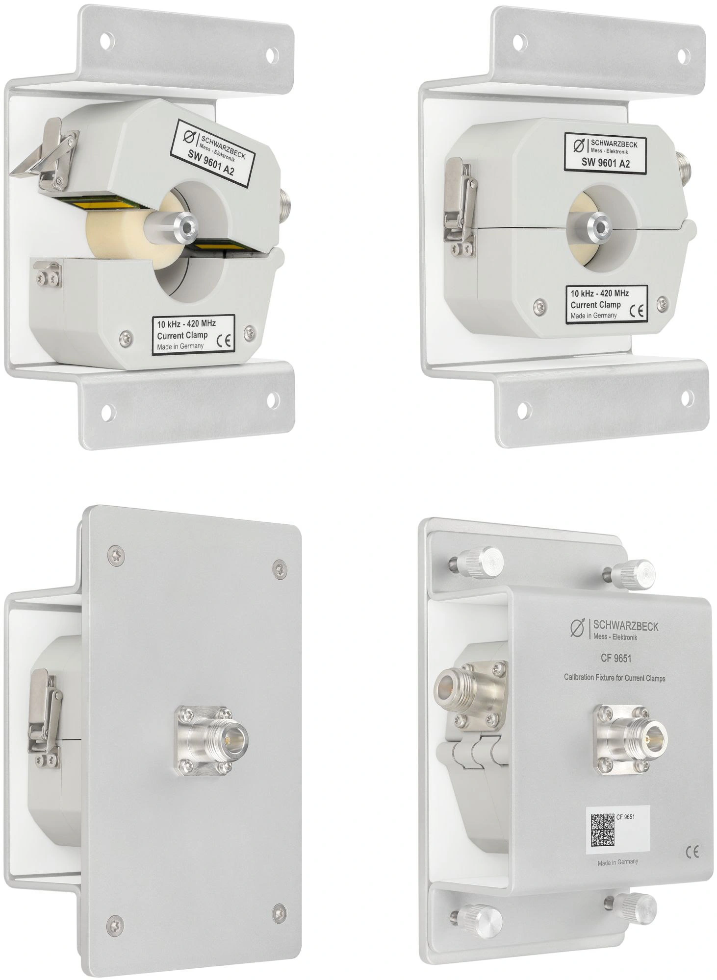
The CF 9651 supports transfer-impedance and insertion-impedance measurements of SW 9600 Bx and SW 9601 Ax current clamps, plus other probes with comparable dimensions. Its aluminum enclosure and centered conductor provide a repeatable mechanical arrangement.
PARTNER:
MARKETS:
CATEGORIES:
TEST STANDARDS:

Data Sheet
Four knurled screws allow the fixture to open and close without additional tools, making probe insertion and removal straightforward.
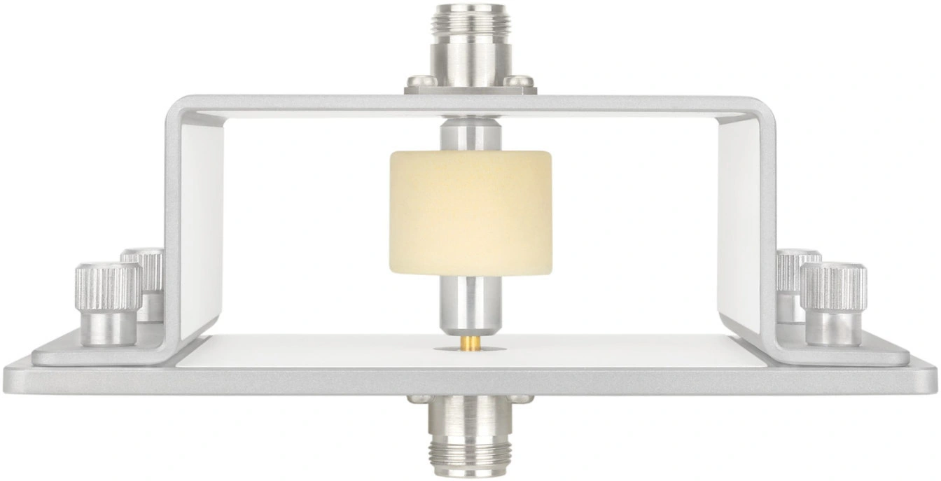
A low-permittivity centering sleeve positions the clamp around the inner conductor. The conductor diameter is 12 mm and the sleeve diameter is 32 mm.
Use the fixture for transfer-impedance or insertion-impedance measurements. Female N connectors are fitted at both ends for coaxial connections.
The manufacturer specifically lists SW 9600 Bx and SW 9601 Ax. Other current probes may be used when their dimensions are comparable.
The datasheet lists maximum current-probe dimensions of 95 × 95 × 45 mm. Check the actual fit and orientation of other probe models before ordering.
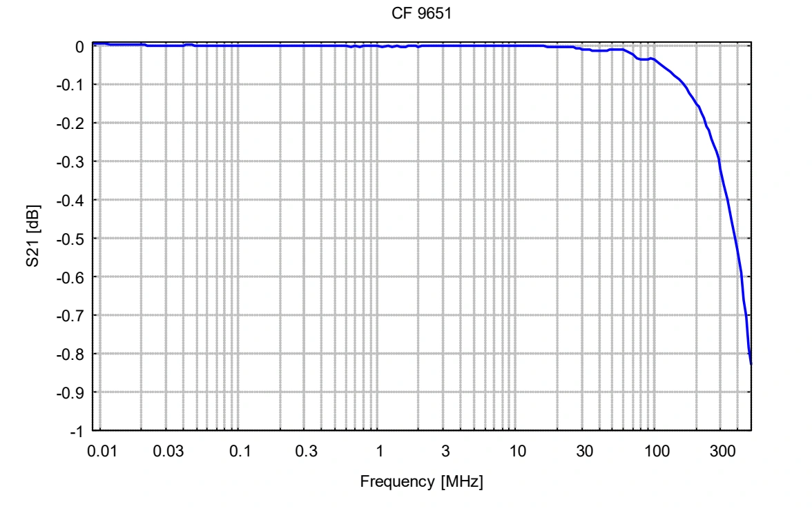
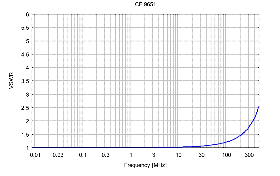
The supplied S21 and VSWR curves show the fixture’s frequency-dependent behavior. The usable range is 10 Hz–500 MHz; the plotted sweep begins at 0.01 MHz.
Functional layout. Use the appropriate calibration and measurement method for the parameter being measured.
Ratings, connectors and mechanical details consolidated from the manufacturer’s product page and Rev. A datasheet.
Read the full datasheet →| Usable frequency range | 10 Hz–500 MHz |
|---|---|
| Connectors | 2 × N female |
| Dimensions | 165 × 100 × 95 mm |
| Maximum current-probe dimensions, as listed | 95 × 95 × 45 mm |
| Inner conductor / listed line diameter | 12 mm |
| Centering-sleeve diameter | 32 mm |
| Weight | Approximately 510 g |
| Material | Aluminum |
| Listed current-clamp families | SW 9600 Bx; SW 9601 Ax |
| Measurement functions | Transfer impedance and insertion impedance |
Extracted from the datasheet with axes, legends and limit lines intact. Typical curves characterize the device; use the stated specifications and unit calibration where applicable.
Original figures extracted from the associated datasheet. Open any image to inspect the full-size figure.
Ask about the CF 9651, compatible accessories and your measurement requirements.
Product inquiries for the United States, Mexico and Canada.