50 Ω RF connection
A female N connector interfaces to coaxial 50 Ω equipment. The clamp has a 32 mm aperture and accepts line diameters up to 31 mm.
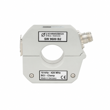
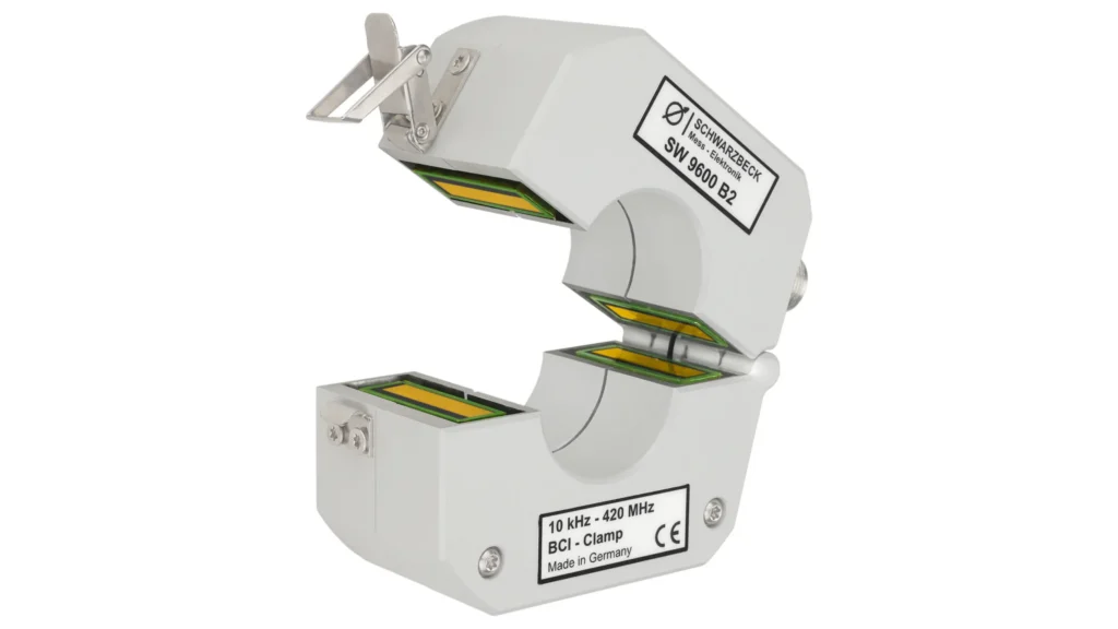
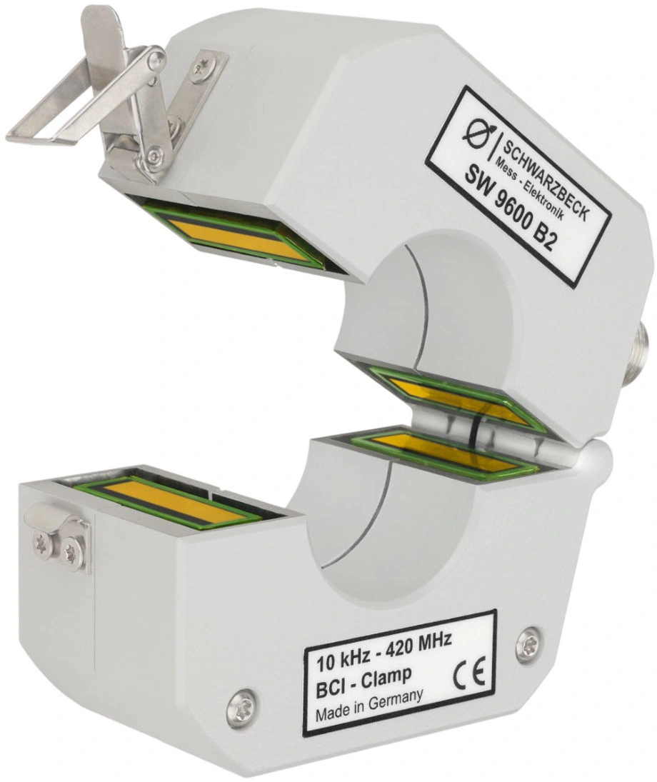
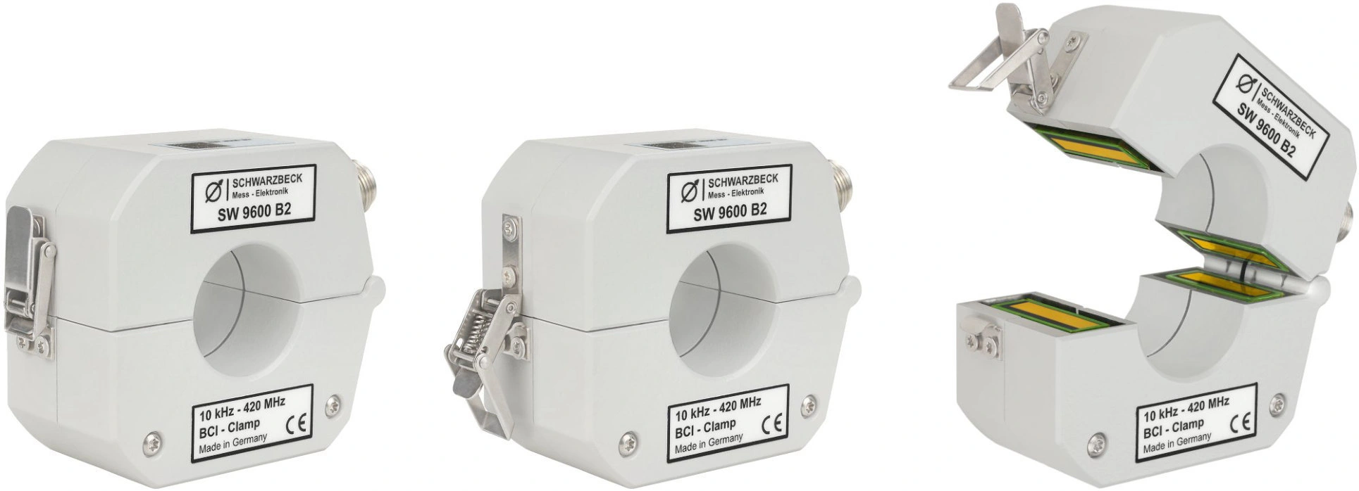
Inject disturbance currents into cables and cable bundles for conducted immunity testing.
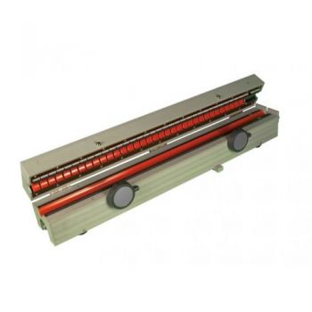
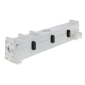
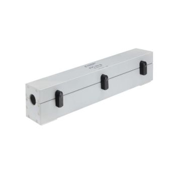
The Schwarzbeck SW 9600 B2 covers 1 kHz–420 MHz and supports up to 30 W CW RF input. Its split-core design accepts cables up to 31 mm in diameter, connects through a 50-ohm N-female interface, and includes individual transfer-impedance calibration data.
PARTNER:
MARKETS:
CATEGORIES:
TEST STANDARDS:

SW 9600 B2 Datasheet
A female N connector interfaces to coaxial 50 Ω equipment. The clamp has a 32 mm aperture and accepts line diameters up to 31 mm.
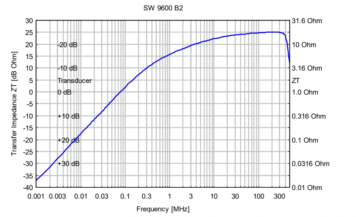
Each unit is supplied with individually measured transfer-impedance data. The curves below show published datasheet characteristics; use the supplied unit data for a specific measurement.
The manufacturer identifies ISO 11452-4, RTCA DO-160 and IEC/EN 61000-4-6 as examples of standards describing immunity testing with current clamps.
The 30 W CW limit applies to RF power entering the clamp. The approximately 300 A rating applies to current in the enclosed conductor at DC to 400 Hz; it is not an injected RF-current specification.
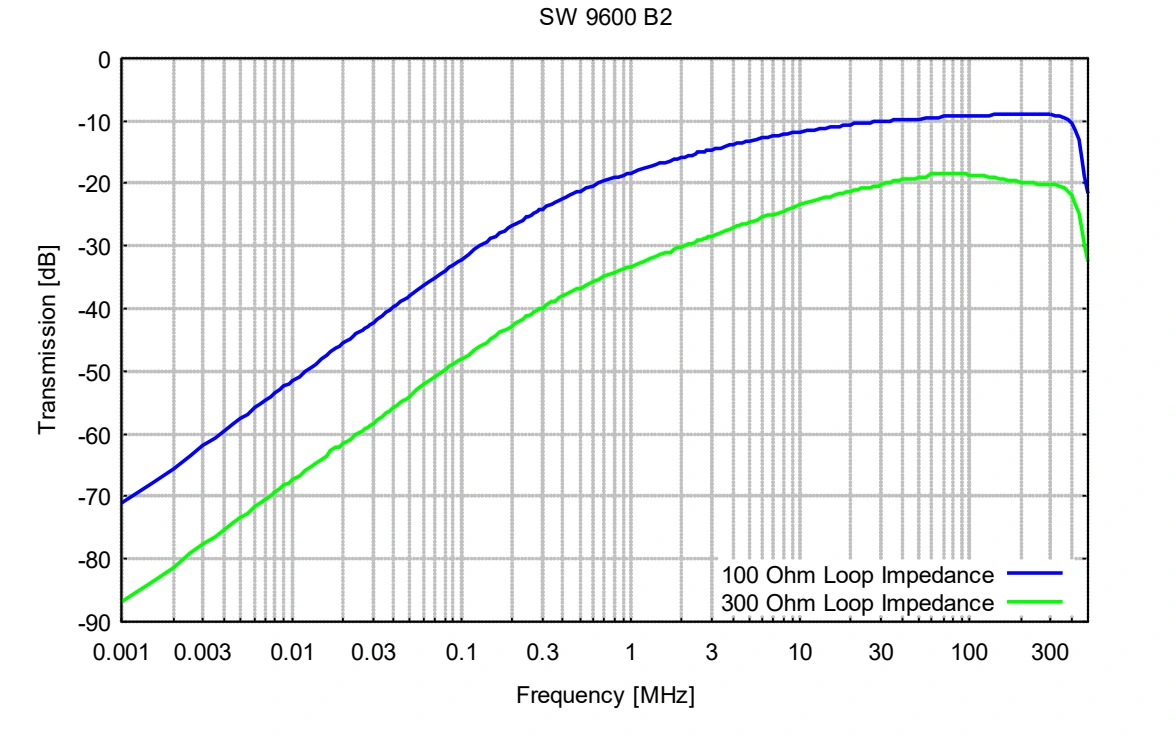
The datasheet compares transmission for 100 Ω and 300 Ω loop impedances. The resulting injected current depends on the test circuit, so the transfer curve alone is not a guaranteed current level.
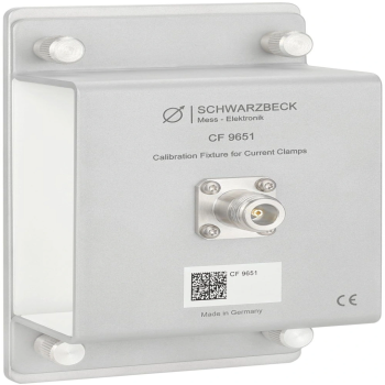
The optional CF 9651 is designed for transfer-impedance and insertion-impedance measurements with SW 9600 Bx and SW 9601 Ax clamps.
The clamp couples the RF signal inductively. The 100 Ω and 300 Ω transmission curves below illustrate the influence of loop impedance.
Ratings, connectors and mechanical details consolidated from the manufacturer’s product page and Rev. A datasheet.
Read the full datasheet| Usable frequency range | 1 kHz–420 MHz |
|---|---|
| RF connector | N female; 50 Ω system |
| Typical transfer impedance at 8 kHz | −20 dBΩ |
| Typical transfer impedance at 80 kHz | 0 dBΩ |
| Typical transfer impedance at 1 MHz | 15 dBΩ |
| Typical transfer impedance at 30–400 MHz | 25 dBΩ |
| Maximum RF input power | 30 W CW |
| Maximum conductor current | Approximately 300 A, DC–400 Hz |
| Transformation ratio | 1:2 |
| Primary inductance | Typical 3.7 µH at 100 kHz |
| Maximum line diameter | 31 mm |
| Aperture | 32 mm |
| Dimensions | 104 × 45 × 79 mm |
| Weight | Approximately 600 g |
| Calibration data | Individual transfer-impedance data supplied |
| Optional calibration fixture | CF 9651 |
Extracted from the datasheet with axes, legends and limit lines intact. Typical curves characterize the device; use the stated specifications and unit calibration where applicable.
Original figures extracted from the associated datasheet. Open any image to inspect the full-size figure.
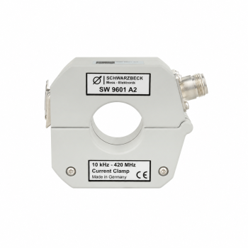
It is designed primarily to inject disturbance current for BCI immunity tests. The SW 9601 A2 is the related RF current-measurement clamp.
No. The curves show published reference characteristics. Each clamp is delivered with its own transfer-impedance calibration data.