Repeatable closure
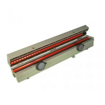
Spring-loaded stainless steel fasteners close a split toroidal core inside a precision-machined aluminum enclosure. The aperture is 32 mm.
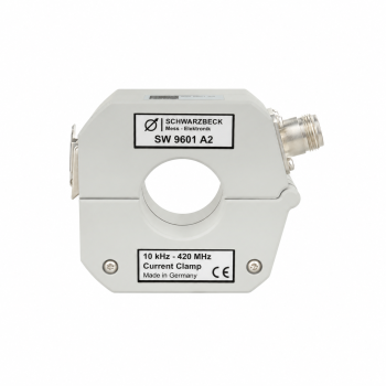
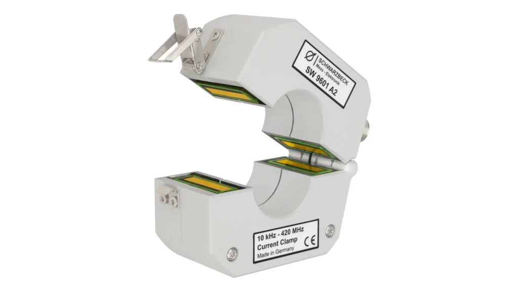
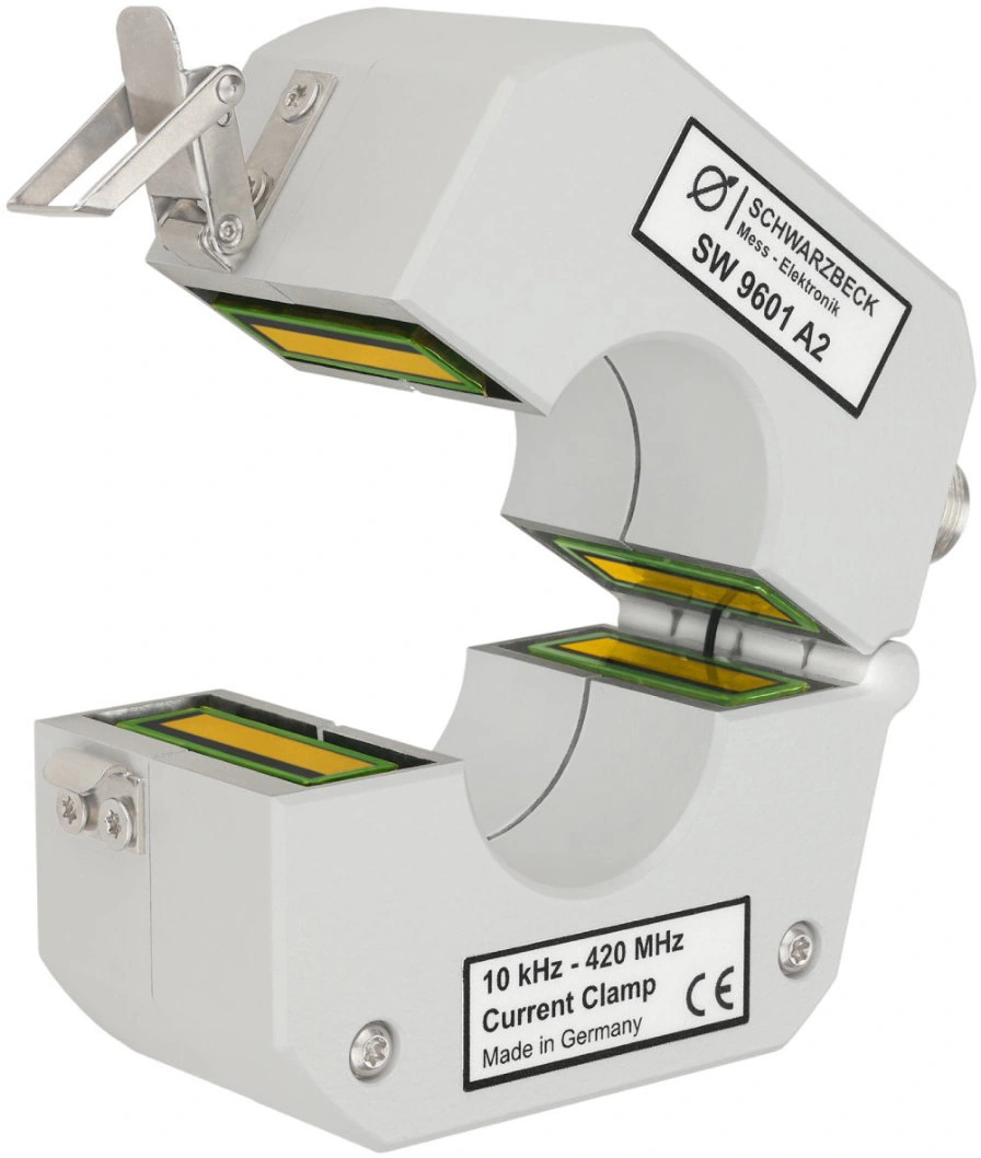
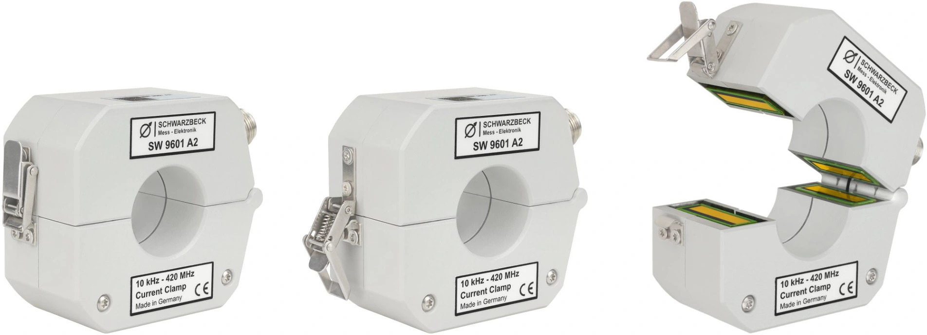
Measure RF disturbance currents on cables and cable bundles.
The Schwarzbeck SW 9601 A2 is a shielded split-core RF current transformer covering 1 kHz–420 MHz. It accepts cables up to 31 mm in diameter, connects to 50-ohm instruments through an N-female connector, and includes individual transfer-impedance calibration data.
PARTNER:
MARKETS:
CATEGORIES:
TEST STANDARDS:

SW 9601 A2 Datasheet
Spring-loaded stainless steel fasteners close a split toroidal core inside a precision-machined aluminum enclosure. The aperture is 32 mm.
The manufacturer lists disturbance-current measurements associated with CISPR 16-2-1, ISO 11452-4, RTCA DO-160, MIL-STD-461 G and IEC/EN 61000-4-6.
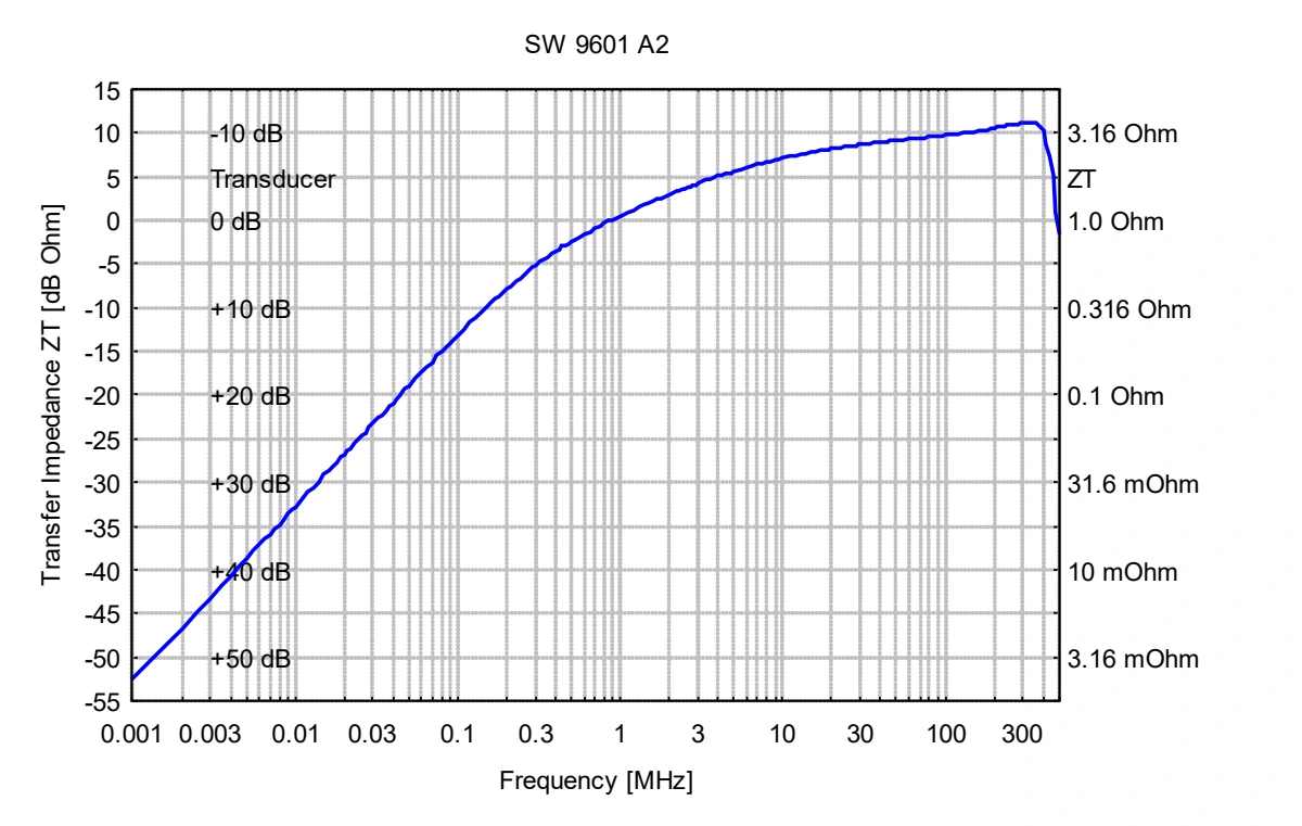
Use the individual calibration data supplied with the clamp to correct the instrument reading. Published datasheet values below describe the reference response, not the calibration of every unit.
At a 50 Ω measurement input: I [dBµA] = U50 [dBµV] − ZT [dBΩ]. Subtract the transfer impedance at the measurement frequency from the measured voltage.
The specification lists approximately 0 dBΩ at 1 MHz and 10 dBΩ at 100 MHz. The detailed published table contains 0.54 dBΩ and 9.75 dBΩ at those frequencies, respectively.
The optional CF 9651 fixture supports transfer-impedance and insertion-impedance measurements for this clamp family.
I [dBµA] = U50 [dBµV] − ZT [dBΩ]. Use the transfer impedance for the actual frequency and clamp.
Conversion from the manufacturer datasheet. U50 is the voltage measured across a 50 Ω input.
Ratings, connectors and mechanical details consolidated from the manufacturer’s product page and Rev. A datasheet.
Read the full datasheet| Usable frequency range | 1 kHz–420 MHz |
|---|---|
| Connector | N female; 50 Ω measuring system |
| Typical transfer impedance at 1 MHz | 0 dBΩ |
| Typical transfer impedance at 100 MHz | 10 dBΩ |
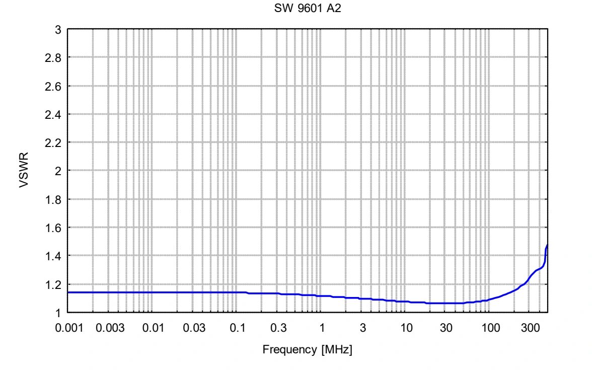
| VSWR, specification summary | Typical <1.3; see frequency-dependent plot |
| Maximum conductor current | Approximately 300 A, DC–400 Hz |
| Transformation ratio | 1:2 |
| Maximum line diameter | 31 mm |
| Aperture | 32 mm |
| Dimensions | 104 × 45 × 79 mm |
| Weight | Approximately 600 g |
| Calibration data | Individual transfer-impedance data supplied |
| Optional calibration fixture | CF 9651 |
Extracted from the datasheet with axes, legends and limit lines intact. Typical curves characterize the device; use the stated specifications and unit calibration where applicable.
Original figures extracted from the associated datasheet. Open any image to inspect the full-size figure.
For a 50 Ω input, subtract transfer impedance in dBΩ from voltage in dBµV to obtain current in dBµA.
The summary lists typical VSWR below 1.3, but the plotted response rises near the top of the range. Consult the full curve for the frequency of interest.
Ask about the SW 9601 A2, compatible accessories and your measurement requirements.
Product inquiries for the United States, Mexico and Canada.