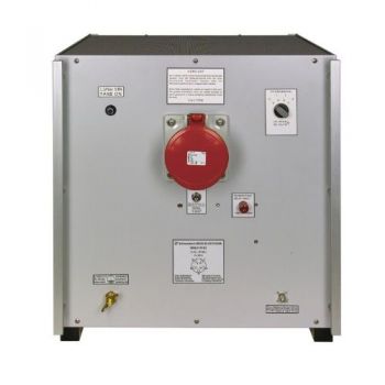
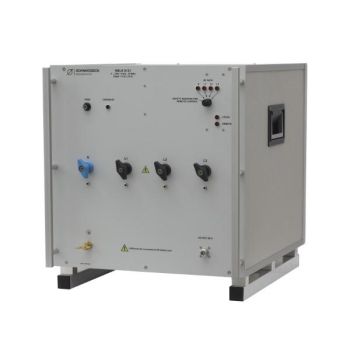
NSLK 8126, 9 kHz - 30 MHz, 250V / 16A, 50 µH, 4 Path LISN
- High Current 4 path LISN (3-Phase & Single-Phase)
- Line Impedance Stabilisation Network
- Connector: CEE plug (IEC 60309) & CEE 7/4
- 9 kHz to 30 MHz
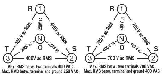
- 250/400 VAC, 400 VDC, 16 A (16A for CEE 7/4)
- (50 µH+5 Ω) || 50 Ω
- CISPR 16-1-2
PARTNER:
MARKETS:
CATEGORIES:
TEST STANDARDS:

Data Sheet
SPECIFICATIONS
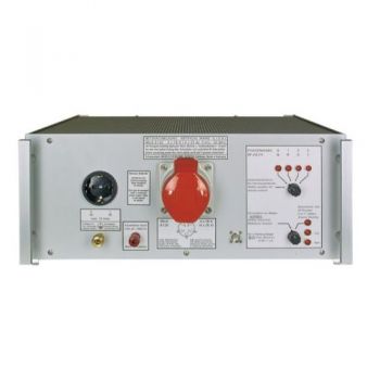
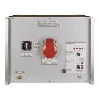
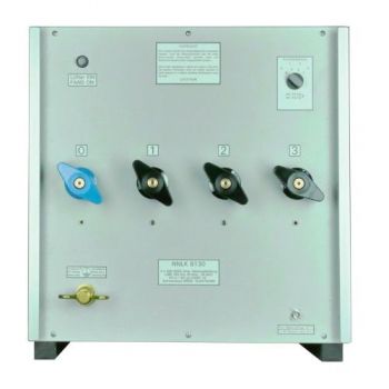
NSLK 8126, 9 kHz - 30 MHz, 250 VAC / 16A, 50 µH, 4 Path LISNThe purpose of a LISN is to provide the device under test with energy, to carry the interference voltage to the EMI measurement receiver, and to load the RF emitted by the device under test with standardized impedance. The NSLK 8126 is equipped with a 250 μH choke as well as a 50 μH choke which is connected in series for each path. The 250 μH choke provides an excellent decoupling between the power supply and the device under test starting at 9 kHz. Important! When using the Schuko connector the operator has to make sure that the maximum current is limited to 16 A at the supply side. When using the 32A CEE connector the current has to be limited to 16 A at the supply side. There is no fuse built into this LISN to protect the device under test! The device under test has to be connected to the Schuko socket or the CEE socket at the front panel. The maximum current that can be drawn is 16 A for each path when using the CEE connector and 16 A when using the Schuko socket. The maximum voltage that can be applied is 250 VAC or 400 VDC.
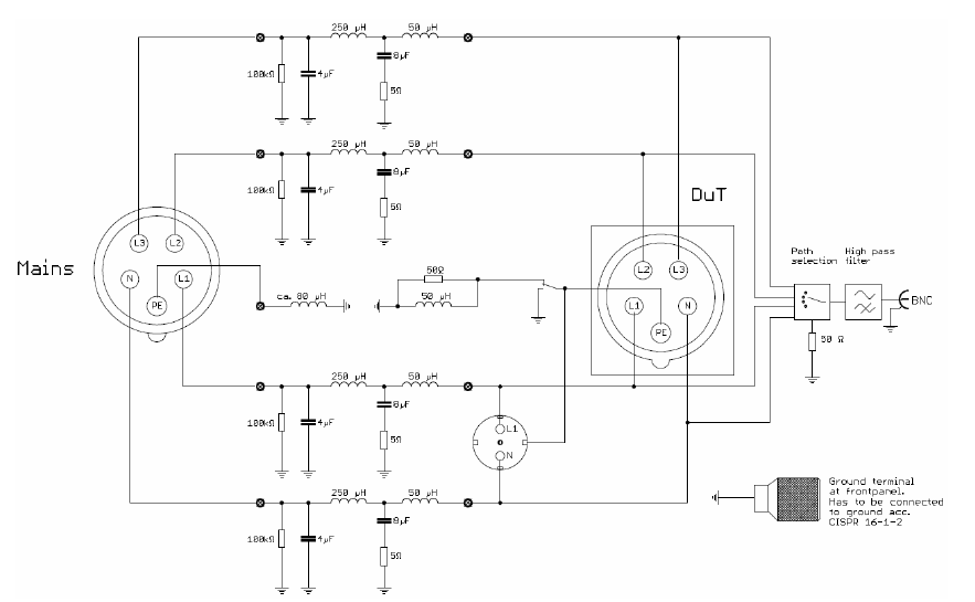
Protective earth switch Using the switch labeled with “Safety ground” you can either put the protection earth of the Schuko socket straight to the ground or in series with a parallel connection of a 50 μH choke and a 50 Ω resistor. Thus the protecting function of the protecting earth connector is ensured as long as the LISN is connected to the earth properly. A protective earth conductor that is decoupled RF-wise via the choke simulates the utilization of long cables. Since some interference suppression solutions are based on the protective ground conductor potential the emission of the device under test could vary depending on the switch setting. If an „artificial hand“ has to be connected to the equipment under test, a copper foil wrapped around the handle of the device under test has to be connected to the screw terminal labeled with “Hand Simulation”.
Options: Option RC for LISN: Remote Control with built-in power supply. LISN can be controlled by R&S or Schwarzbeck code, including remote control cable for your receiver type (Please specify your receiver type!). LISN can be selected from the R&S receiver menu or in the EMC32 software like an R&S LISN. No programming of the user interfaces necessary. Functions: path selection and PE grounded or via choke.
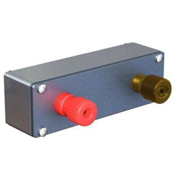
The NSLK 8126 is equipped with a high pass filter but not with a pulse limiter. The EMI receiver should therefore be protected against overload. The VTSD 9561 F is an external pulse limiter that is suitable for this purpose. If the amplitude of the disturbance voltage exceeds values which could be dangerous for the EMI receiver input the pulse limiter will cut these pulses. This causes additional spectral lines in the frequency domain (“phantom spectral lines”). The excess-pulse-energy illuminates an electric bulb. If the bulb glows or lights up the measurement is not valid because of the phantom spectral lines. In such a case more attenuation must be used at the measuring port of the LISN. An external attenuator must be dimensioned sufficiently especially under the presence of strong harmonics of the mains frequency |


OTHER PRODUCTS IN THE SAME CATEGORY:
NSLK 8117, 9 kHz - 30 MHz, 250V / 10A, 50 µH, 2 Path LISN
NSLK 8126, 9 kHz - 30 MHz, 250V / 16A, 50 µH, 4 Path LISN
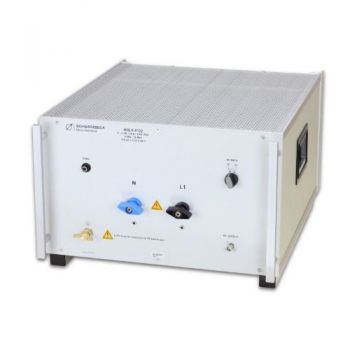
NSLK 8127, 9 kHz - 30 MHz, 250V / 16A, 50 µH, 2 Path LISN
NSLK 8163, 9 kHz - 30 MHz, 400V / 63A, 50 µH, 4 Path LISN
Artificial Hand
NSLK 8128, 9 kHz - 30 MHz, 250V / 32A, 50 µH, 4 Path LISN
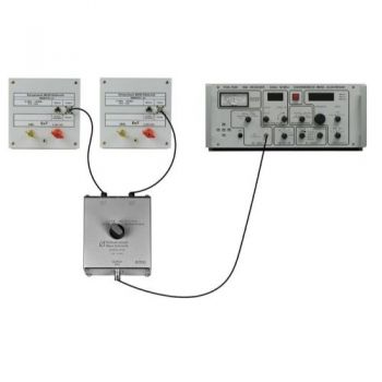
CMDM 8700 B Common mode / Differential mode switch
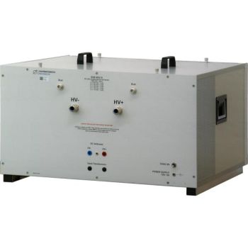
BNB 8652 B HV Line Stabilization Network
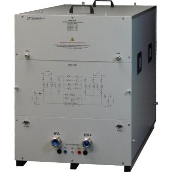
BNB 8656 HV Line Stabilization Network
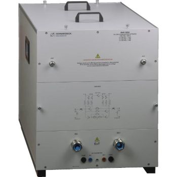
BNB 8654 C HV Line Stabilization Network
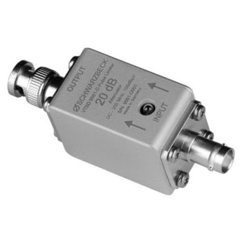
VTSD 9561 D, 20dB, Diode Pulse Limiter
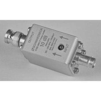
VTSD 9561 F, 10dB, Diode Pulse Limiter
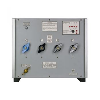
NNLK 8121, 9 kHz - 30 MHz, 400V / 100A, 50 µH, 4 Path LISN
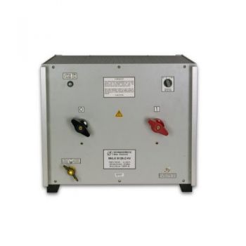
NNLK 8122, 9 kHz - 30 MHz, 1000VDC / 50A, 50 µH, 2 Path LISN
NNLK 8129, 150 kHz - 30 MHz, 400V / 200A, 50 µH, 4 Path LISN
NNLK 8129-2 HV, 150 kHz - 30 MHz, 1000V / 200A, 50 µH, 2 Path LISN
NNLK 8130, 150 kHz - 30 MHz, 400VAC/400A, 50 µH, 4 Path LISN
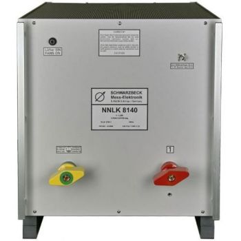
NNLK 8140, 150 kHz - 30 MHz, 1000V/800A, 50 µH, Single Path LISN
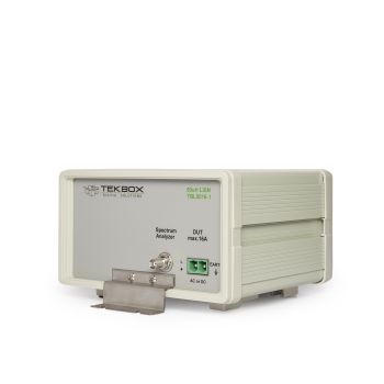
TBL5016-1 50uH 16A Line Impedance Stabilization Network LISN

